Brushless motor drive device

a brushless motor and drive device technology, applied in the direction of electronic commutators, generating/distributing signals, programme control, etc., can solve the problems of inability to detect an error in the ad converter circuit, the deviation of the target value, and the inability to accurately calculate the current value detected, so as to reduce rotation errors and torque errors, reduce air volume and driving noise variations, and high precision

Inactive Publication Date: 2017-03-16
PANASONIC INTELLECTUAL PROPERTY MANAGEMENT CO LTD
View PDF8 Cites 0 Cited by
  • Summary
  • Abstract
  • Description
  • Claims
  • Application Information

AI Technical Summary

Benefits of technology

[0011]In the brushless motor drive device in accordance with the present invention, the conversion error of the AD converter circuit can be calculated and used either to diagnose faults in the AD converter circuit or to correct an output value of the AD converter circuit and then to input the value into software with high precision. This allows high-precision calculation of the current value detected by the current detection circuit so as to reduce rotation errors and torque errors, thereby reducing variations in the air volume and driving noise of the cooling fan.
[0012]It is known that typical AD converter circuits have a lower effective number of bits and lower conversion characteristics as their input analog signals have a higher frequency. To deal with such characteristics of the AD converter circuits, the brushless motor drive device in accordance with the present invention calculates the conversion error of the AD converter circuit by using a pulse signal with a changing frequency. More specifically, unlike the static method of applying a DC voltage to the input of the AD converter circuit and calculating the conversion error while changing the voltage, the motor drive device in accordance with the present invention can calculate the conversion error based on the realistic conversion characteristics by using the pulse signal with the changing frequency. Thus, the device in accordance with the present invention can diagnose faults in the AD converter circuit and correct the output value of the circuit with high precision by simply applying a pulse signal to the RC filter.
[0013]As described above, the brushless motor drive device in accordance with the present invention does not require a large motor or a large circuit board to ensure enough margin for the rotation error or the torque error, so that the cooling fan can be smaller and lighter in weight.

Problems solved by technology

In this case, a similar error may occur in the actual rotation speed and torque that are to be calculated and cause a deviation from a target value.
However, in PTL 1, when the voltage for diagnosis is within the predetermined range, an error in the AD converter circuit makes it impossible to accurately calculate the current value detected by the current detection circuit and causes a torque error.
Meanwhile, in PTL 2, the error rate of the reference clock can be used to correct the rotation speed, but it is impossible to detect an error in the AD converter circuit.

Method used


Image

  • Brushless motor drive device
  • Brushless motor drive device
  • Brushless motor drive device

Examples


first exemplary embodiment

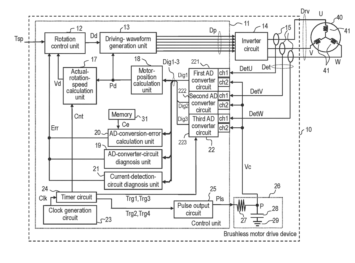
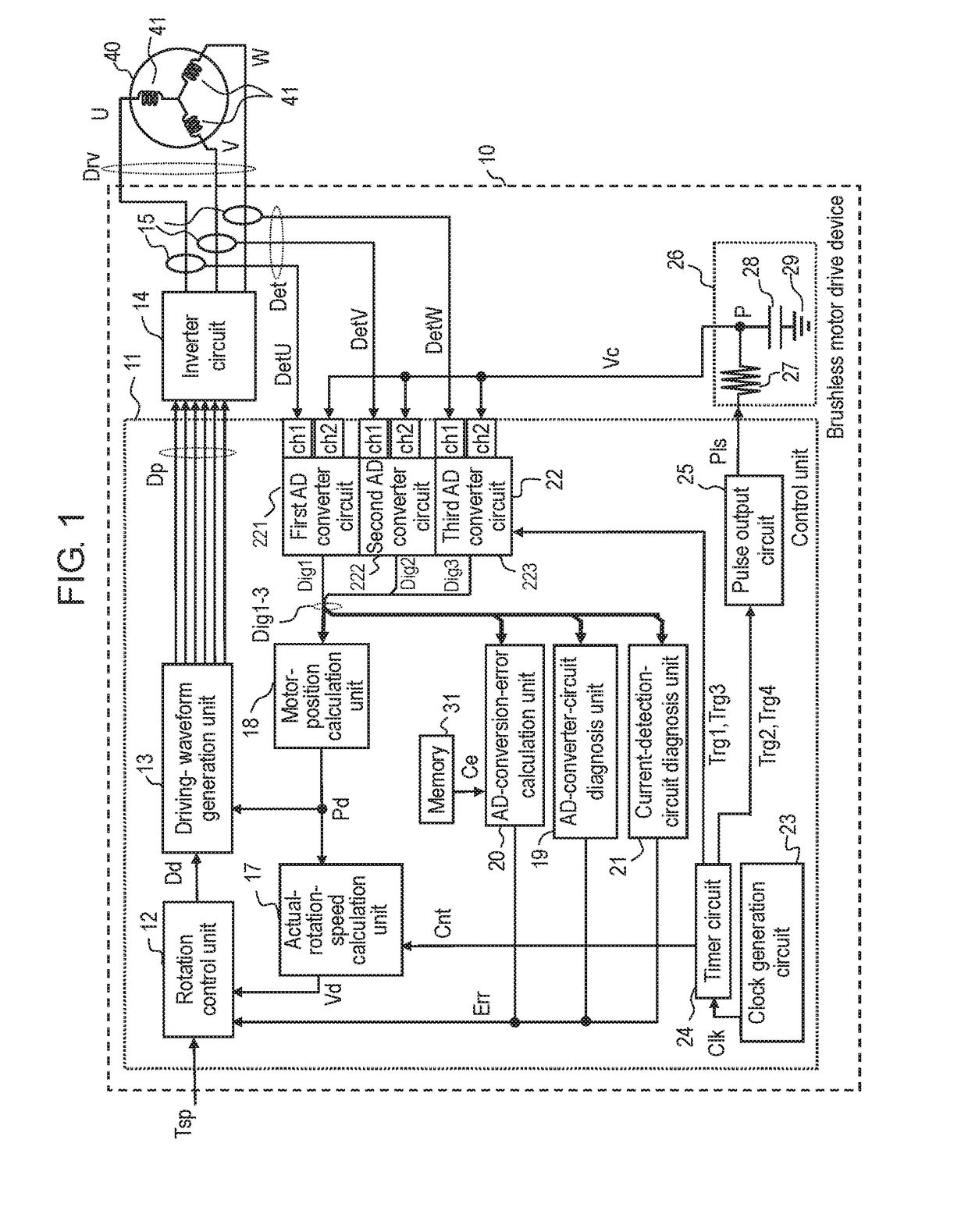
[0020]FIG. 1 is a block diagram showing a configuration of brushless motor drive device 10 in accordance with a first exemplary embodiment of the present invention. In the example of FIG. 1, brushless motor drive device 10 is connected to brushless motor 40. Device 10 drives motor 40 to control its rotation in accordance with an external command.

[0021]Motor 40 includes a stator with coils 41 whose windings are wound around the stator core, and a rotor configured to rotate around the shaft when coils 41 are energized and driven. The present exemplary embodiment describes a case in which motor 40 includes coils 41 of three phases U, V, and W, and device 10 rotates these phases using pulse-width modulated (PWM) drive signals Dry.

[0022]As shown in FIG. 1, device 10 includes current detection circuits 15, inverter circuit 14, control unit 11, and RC filter 26.

[0023]Device 10 receives as one of the commands from an external host controller (not shown) a rotation speed / torque command Tsp, ...

second exemplary embodiment

[0088]FIG. 4 is a block diagram showing the configuration of brushless motor drive device 60 in accordance with a second exemplary embodiment of the present invention. In the example of FIG. 4, device 60 is connected to motor 40. In the same manner as in the first exemplary embodiment, device 60 drives motor 40 to control its rotation in accordance with an external command.

[0089]In the present exemplary embodiment, control unit 61 includes correction-table generation unit 32 and correction table 33, which are not included in control unit 11 in accordance with the first exemplary embodiment. The other components are identical to those contained in the first exemplary embodiment, and hence, they are not described in detail again.

[0090]As described in the first exemplary embodiment, AD-conversion-error calculation unit 20 calculates the offsets Ados, which are the conversion errors from the reference value in AD conversion, using the output values Dig produced in response to the input ...


PUM


Abstract

A brushless motor drive device includes the following: an inverter circuit configured to energize and drive the winding of a brushless motor; a current detection circuit configured to detect the current value of the winding; a control unit configured to control the rotation of the motor; and an RC filter including a resistor and a capacitor. The control unit includes the following: a drive control unit configured to generate a signal to drive the inverter; a clock generation circuit configured to generate a clock pulse to be used as a reference for an operation period; a pulse output circuit configured to generate a pulse signal with a changing frequency based on the clock pulse and to apply the pulse signal to the RC filter; an AD converter circuit connected to the capacitor of the RC filter and the current detection circuit; and an AD-conversion-error calculation unit configured to calculate the conversion error of the AD converter circuit. The AD-conversion-error calculation unit calculates the conversion error based on the difference between the output value of the AD converter circuit produced in response to an input of the voltage of the capacitor and an AD-converted value calculated from the charging time of the capacitor.

Description

TECHNICAL FIELD[0001]The present invention relates to a brushless motor drive device for driving a brushless motor. The invention particularly relates to a brushless motor drive device having the function of diagnosing faults in AD (analog-digital) converter circuits and current detection circuits and then generating correction values. The diagnosis is made before variations in motor control circuits cause a difference between a commanded torque and an actual torque, which may be caused by the above-mentioned faults.BACKGROUND ART[0002]Cooling fans typically used in refrigerators include a brushless motor because of its features of long life and energy saving. The fans are controlled to follow their air volume and driving noise depending on the ambient temperature and the temperature of an object to be cooled. It is known that variations in the air volume depend on variations in the rotation speed of the motor attached to the impeller, whereas the driving noise depends on the rotati...

Claims


Application Information

Patent Timeline
Patent Type & Authority Applications(United States)
IPC IPC(8): H02P6/28
CPCH02P6/28G06F1/04H02P29/04H02P6/18G05B19/409H02P21/22H02P23/00G06F11/1604
Inventor SATO, DAISUKE
Owner PANASONIC INTELLECTUAL PROPERTY MANAGEMENT CO LTD
Why Eureka
Try Eureka