
Electronic device and method for displaying an image on head mounted display device

a technology of display device and display device, which is applied in the direction of static indicating device, instruments, optical elements, etc., can solve the problems of high latency, system delay, motion sickness, nausea and/or the like, and achieve the effect of reducing the inconvenience of using the hmd device, reducing the latency of image display, and significantly reducing the delay of the entire system

Inactive Publication Date: 2017-03-16
SAMSUNG DISPLAY CO LTD
View PDF3 Cites 24 Cited by
  • Summary
  • Abstract
  • Description
  • Claims
  • Application Information

AI Technical Summary

Benefits of technology

The patent text describes a technology for reducing latency and improving the realism of augmented reality experiences by using a high-speed image processing device. The device includes a processor for performing filtering and smoothing to eliminate noise caused by movement. Additionally, the display driver performs the XY offset at the same time as the image processing, resulting in a faster display of images and a significant reduction in latency and system delay. This technology aims to decrease the inconvenience of using the HMD device and provide a more immersive user experience.

Problems solved by technology

However, a number of processing steps that are used to update an image in response to detected motion may cause a high latency.
The high latency (and a system delay) is perceived by a user that is using the HMD device, such that motion sickness, nausea and / or the like may occur.
Further, latency is generated in overlaying a background image and an object image, such that realism of the see-through display (e.g., synchronization between a virtual world and the real world) is decreased.
Although motion prediction methods and frame interleaving methods have been researched for achieving low latency, these algorithms cannot account for unexpected or sudden movements, and cannot reduce an overall system delay.

Method used


Image

  • Electronic device and method for displaying an image on head mounted display device
  • Electronic device and method for displaying an image on head mounted display device
  • Electronic device and method for displaying an image on head mounted display device

Examples


Embodiment Construction

[0039]Exemplary embodiments will be described more fully hereinafter with reference to the accompanying drawings, in which various embodiments are shown.

[0040]It will be understood that, although the terms “first”, “second”, “third”, etc., may be used herein to describe various elements, components, regions, layers, and / or sections, these elements, components, regions, layers, and / or sections should not be limited by these terms. These terms are used to distinguish one element, component, region, layer or section from another element, component, region, layer or section. Thus, a first element, component, region, layer, or section discussed below could be termed a second element, component, region, layer, or section, without departing from the spirit and scope of the present invention.

[0041]The terminology used herein is for the purpose of describing particular embodiments and is not intended to be limiting of the present invention. As used herein, the singular forms “a” and “an” are...


PUM


Abstract

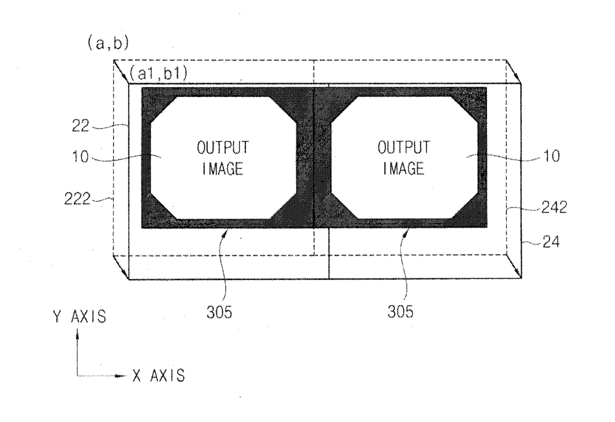
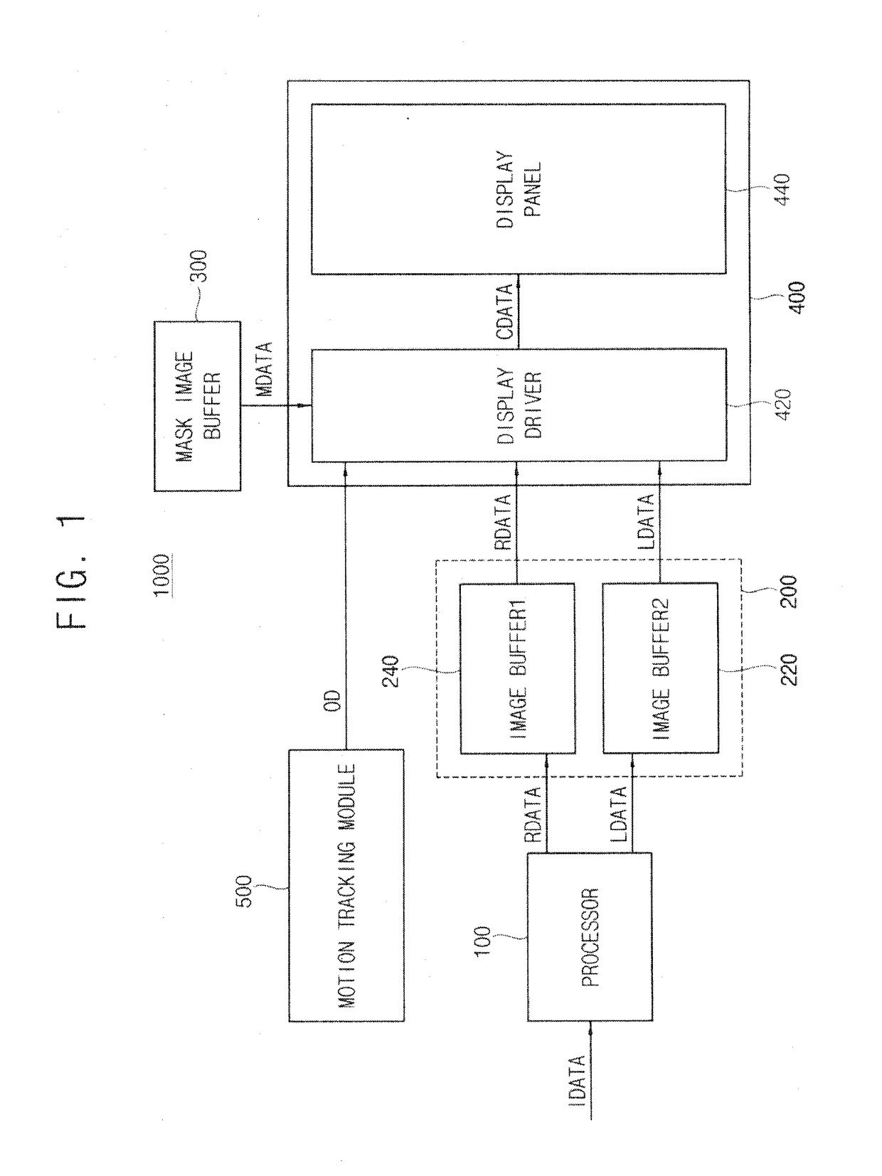
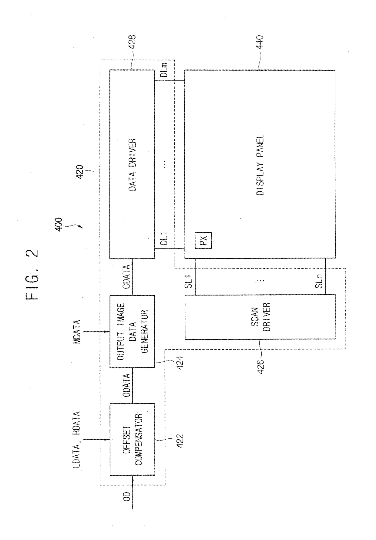
An electronic device includes a processor configured to generate an oversized image by rendering an externally received input image, an image buffer configured to store the oversized image, a mask image buffer configured to store a mask image, which is smaller than the oversized image, a display device configured to apply, in real time, an XY offset to the oversized image based on orientation data to generate an offset image, and blend the offset image with the mask image to display an output image, which is smaller than the oversized image, and a motion tracking module configured to sense a movement of the display device and generate the orientation data.

Description

CROSS REFERENCE TO RELATED APPLICATION[0001]This application claims priority to, and the benefit of, Korean Patent Applications No. 10-2015-0130778, filed on Sep. 16, 2015 in the Korean Intellectual Property Office (KIPO), the disclosure of which is hereby incorporated by reference herein in its entirety.BACKGROUND[0002]1. Field[0003]Example embodiments of the inventive concept relate to electronic devices having a head mounted display (HMD) device, and methods for displaying an image on the HMD device.[0004]2. Discussion of Related Art[0005]A display device, such as a head-mounted display (HMD) device, may be configured to provide augmented reality experiences by displaying virtual images over a real-world background that is viewable through the display. As a user of a see-through display device changes their location and / or orientation in a use environment, the device detects the movements of the user, and updates displayed images accordingly.[0006]However, a number of processing ...

Claims


Application Information

Patent Timeline
Patent Type & Authority Applications(United States)
IPC IPC(8): G06T3/40G02B27/01G06F3/01
CPCG06T3/40G06F3/017G02B2027/0134G02B27/0172G02B2027/014G02B27/0179G06F3/011G06F3/012G02B27/017G02B2027/0198G02B2027/0187G09G3/002G09G5/397G09G2310/04G09G2340/045G09G2340/14G09G2360/18G09G5/34
Inventor FOLSE, NICHOLAS
Owner SAMSUNG DISPLAY CO LTD
Learn More