
Xenon suppression filter for spectrometry

Inactive Publication Date: 2017-03-16
OCEAN OPTICS
View PDF1 Cites 1 Cited by
  • Summary
  • Abstract
  • Description
  • Claims
  • Application Information

AI Technical Summary

Benefits of technology

The invention is a filter device that improves the suppression of light from a Pulsed Xenon light source used for spectrometry. It consists of a combination of a Variable Longpass Order-Sorting filter and a Dichroic Balancing filter coated on a fused Silica substrate. This configuration helps to achieve better light suppression and signal quality in the UV regions.

Problems solved by technology

This can present itself as a problem when a user desires to take measurements outside of this range.

Method used


Image

  • Xenon suppression filter for spectrometry
  • Xenon suppression filter for spectrometry
  • Xenon suppression filter for spectrometry

Examples


Embodiment Construction

[0009]As discussed the disclosed device improves the suppression of light from a Pulsed Xenon light source for spectrometry by combining a Variable Longpass Order-Sorting filter with a Dichroic Balancing filter by coating them both on a fused Silica substrate.

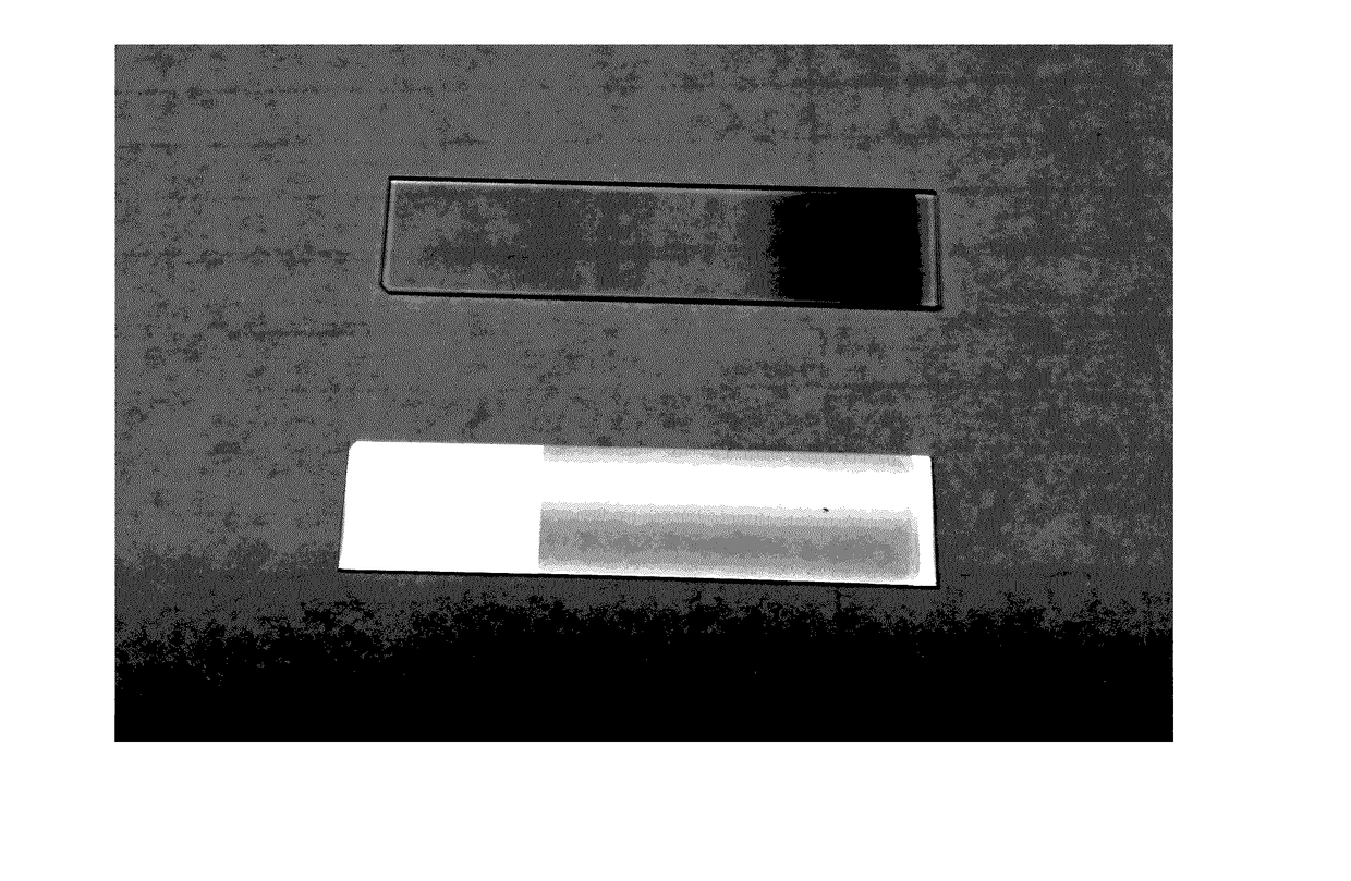
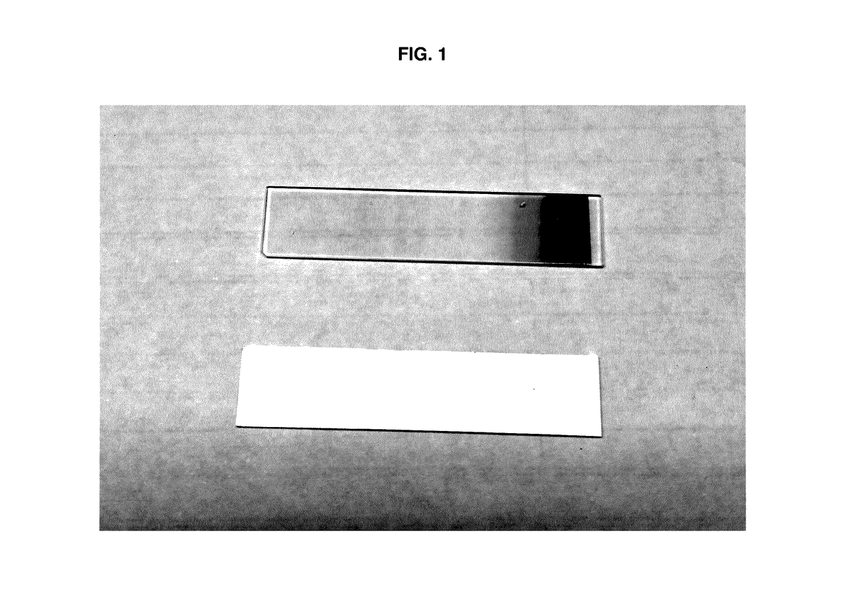
[0010]As shown in FIG. 1 a preferred embodiment of this device is constructed by coating the Dichroic Balancing filter (shown at bottom of FIG. 1) on the opposite side of the Variable Longpass Order-Sorting filter substrate (shown at top of FIG. 1), or, in an alternate embodiment, by combining the two filters using two substrates. The substrates are made of fused silica to avoid any attenuation of signal in the UV regions.

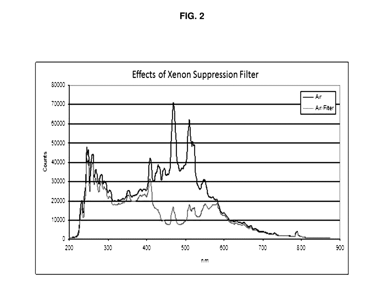
[0011]As shown in FIG. 2 the device of this disclosure suppresses the more intense light output in the range from 400-600 nm from the Pulsed Xenon light source.

[0012]Since certain changes may be made in the above described Xenon suppression filter without departing from the scope of the invention herein involv...


PUM


Abstract

A device for improving the suppression of light from a Pulsed Xenon light source for spectrometry by combining a Variable Longpass Order-Sorting filter with a Dichroic Balancing filter coated on a fused Silica substrate is disclosed.

Description

CROSS-REFERENCE TO RELATED APPLICATION[0001]The present application claims the benefit of previously filed co-pending Provisional Patent Application, Ser. No. 62 / 217,078, filed on Sep. 11, 2015.FIELD OF THE INVENTION[0002]The device of this disclosure belongs to the field of manufacture of spectrometer filters. More specifically it is a new Pulsed Xenon light source suppression filter for spectrometry applications.BACKGROUND OF THE INVENTION[0003]Pulsed Xenon or “PX” sources are a great source of light for variety of Spectroscopic applications such as Absorbance, Reflection, and Fluorescence measurements. They produce light energy with a spectral range from approximately 220-750 nm. However, they inherently produce more intense light output in the range from 400-600 nm. This can present itself as a problem when a user desires to take measurements outside of this range. This is because the spectrometer can become saturated with the stronger visible light before the maximum signal can...

Claims


Application Information

Patent Timeline
IPC IPC(8): G02B5/20G01J3/02
CPCG01J3/0229G02B5/208G01J3/0227G01J3/10G01J2003/1213G01J2003/1282
Inventor AVE, PAUL W.
Owner OCEAN OPTICS
Learn More