Decoder and method

Active Publication Date: 2017-03-09
GURULOGIC MICROSYST
View PDF3 Cites 10 Cited by
  • Summary
  • Abstract
  • Description
  • Claims
  • Application Information

AI Technical Summary

Benefits of technology

The technology in this patent allows for efficient and high-quality decoding of data content items without losing any quality during the decoding process. The method can be used with different types of data and can even compress and decompress data for further processing.

Problems solved by technology

However, such images and videos are demanding in respect of data memory capacity and communication system bandwidth that is utilized.
When communication system bandwidth is limited, such images and videos take significant time to communicate.
However, it is highly desirable that encoding methods that provide a degree of data compression should be substantially lossless in relation to information content when generating the compressed data.
In general, many known video codecs are not able to code efficiently extensive areas of images with substantially constant parameters whilst concurrently being able to encode highly spatially detailed areas of the images.
Such relatively smaller blocks are employed because larger sizes of blocks result in inefficient encoding processes, although 16×16 image element blocks are sometimes employed.
Certain types of contemporary encoding can even result in an increase in data size, when error correction features such as parity codes and error correction codes are included.
However, even bigger problems occur along the progress reached in sequencing human genomes and utilizing them in medical research and development.
Yet further, Internet of Things (IoT) concerns devices that process large amounts of data, yet the individual batches of data are typically small in size.
These problems raised by new, disruptive technologies and big data require efficient ways of compression which known coding technology has not been able to sufficiently address.

Method used


Image

  • Decoder and method
  • Decoder and method
  • Decoder and method

Examples


an example

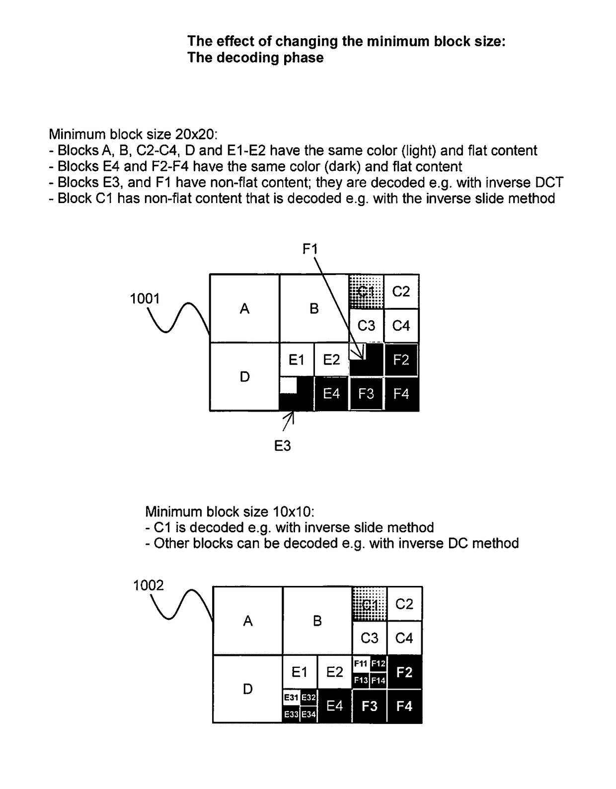
[0155]Simplified example of decoding an encoded image is described below. Based on this embodiment the decoder receives information content from a given encoder (for example as streamed or as file). According to example the information content is in a form of file consisting of following information fields and content:

[0156]Imagesize: 120×80 pixels

[0157]InitialBlocksize: 40×40 pixels

[0158]SplitBit: 0 0 1 0000 0 1 0010 0000 1 1000 0000

[0159]MethodBits: 0 0 1 0 0 0 0 0 0 0 0 0 0 0 0 0 0 0 0 0 0

[0160]Values: 10 10 20 25 15 20 10 10 10 10 10 10 5 10 5 5 5 5 5 5 10 5 5 5

[0161]Where:

[0162]Imagesize describes the size of the image to be decoded. The size of the image can be arbitrary; however, in this specific example it is 120×80 pixels which means that the initial block size is 40×40 because there are 3×2 blocks in the grid in the entire image. InitialBlocksize describes what is a size of “basic” initial blocks. Depending on the implementation the InitialBlocksize can be fixed (such as 4...


PUM


Abstract

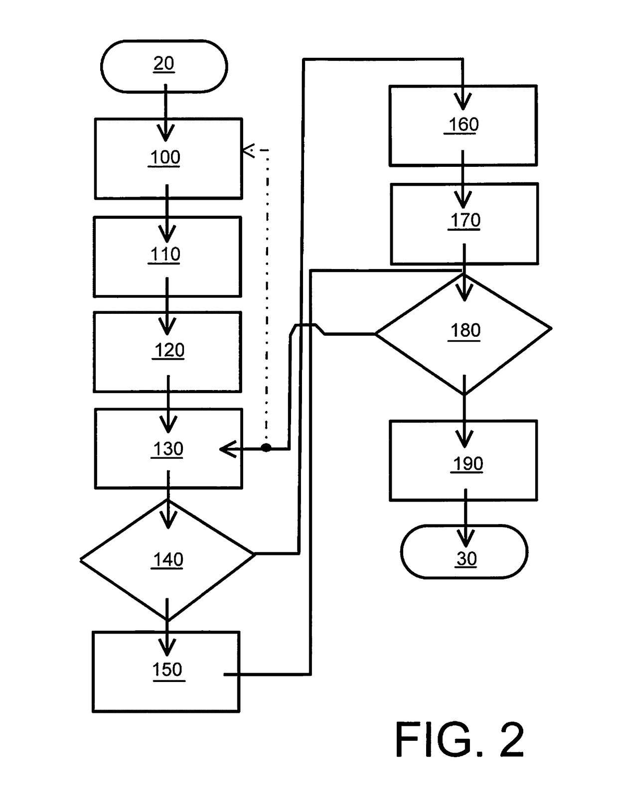
A decoder is operable to decode input data to generate corresponding decoded output data. The decoder includes data processing hardware which is operable to:(a) process the encoded input data to extract therefrom header information indicative of encoded data pertaining to individual blocks and / or packets included in the encoded input data, and information including data indicative of transformations employed to the individual blocks and / or packets;(b) create an initial set of individual blocks and / or packets based on received header data, and preparing a data field in a data storage arrangement for receiving decoded individual block and / or packet content;(c) split or combine individual blocks and / or packets in the data field according to information indicative of splitting / combining;(d) retrieve information describing the transformations and then applying an inverse of the transformations for decoding the encoded and compressed original block and / or packet data to generate corresponding decoded block and / or packet content for populating said data field; and(e) when the encoded input data has been at least partially decoded, outputting data from the data field as the decoded output data.

Description

CROSS REFERENCE TO RELATED APPLICATIONS[0001]This is a continuation-in-part of U.S. patent application Ser. No. 13 / 584,047, filed Aug. 13, 2012, which claims the benefit under 35 USC 119(a) and 37 CFR 1.55 to U.K. Application Serial No. GB 1214400.2 filed Aug. 13, 2012, the entire contents of each of which are incorporated herein by reference.FIELD[0002]The present disclosure relates to decoders for receiving encoded input data and decoding the input data to generate corresponding decoded output data. Moreover, the present disclosure also concerns methods of decoding encoded input data to generate corresponding decoded output data. Furthermore, the present disclosure also concerns software products recorded on non-transitory machine-readable data storage media, wherein the software products are executable upon computing hardware for implementing aforesaid methods.BACKGROUND INFORMATION[0003]Data content is stored and communicated to an increasing extent by contemporary human populat...

Claims


Application Information

Patent Timeline
IPC IPC(8): H04N19/60H04N19/122H04L29/06
CPCH04N19/60H04N19/176H04N19/122H04L69/22H04N21/4394H04N21/44008H04N21/4402H04N19/46H04N19/61H04N19/12H04N19/157H04N19/188H04N21/44004H04N21/4532H04N19/119H04N19/14H04N19/174H03M7/30H04N1/41H04N7/24
Inventor KALEVO, OSSIKARKKAINEN, TUOMAS
Owner GURULOGIC MICROSYST
Why Eureka
Try Eureka