
Catalysts for polyurethane foam polyol premixes containing halogenated olefin blowing agents

a technology of halogenated olefin and catalyst, applied in the field of polyurethane and polyisocyanurate foam, to blowing agents and catalyst systems, can solve the problems of undesirable increase in reaction time, inconvenient use, and undesirable effects, and achieve the effect of negative effect on reaction times and

Inactive Publication Date: 2017-03-09
HONEYWELL INT INC
View PDF5 Cites 4 Cited by
  • Summary
  • Abstract
  • Description
  • Claims
  • Application Information

AI Technical Summary

Benefits of technology

The patent text describes a way to make polyol premixes that can be used to make foam with a long shelf life. By adding certain chemicals to the premix, the foam can be made even if it has been stored for a few weeks or months. This provides a better shelf life for the foam, even if it has been produced using a polyol blend that has been stored for a long time.

Problems solved by technology

If a surfactant is not used in the foaming composition, the bubbles simply pass through the liquid mixture without forming a foam or forming a foam with large, irregular cells rendering it not useful.
However, applicants have found that if the polyol premix composition containing a halogenated olefin blowing agent and a typical amine-containing catalyst is aged, prior to treatment with the polyisocyanate, deleterious effects can occur.
For example, applicants have found that such formulations can produce a foamable composition which has an undesirable increase in reactivity time and / or a subsequent cell coalescence.
The resulting foams are of lower quality and / or may even collapse during the formation of the foam.
It has now been found that one source of the problem observerd by applicants is the reaction of certain amine catalysts with certain hydrohaloolefins.
Although applicants do not wish to be bound by or to any particular theory, it is believed that such reactions have both direct and indirect deleterious effects.
For example, the decomposition reaction depletes the availability of the amine catalyst and hence has a negative effect on reaction times and the quality of foam.
In addition, while applicants believe that all halogenated olefin blowing agents will exhibit some level of the deleterious effects mentioned above, applicants had surprisingly and unexpectedly found that a certain halogenated olefin, particularly monochloro-trifluoropropenes and even more particularly trans-1-chloro-3,3,3-trifluoropropene (1233zd(E)), tend to exhibit only a relatively low level of the deleterious effect, especially when used in combination with catalyst which contains a relatively low level, and preferably no substantial amount of amine-containing catalyst.

Method used


Image

  • Catalysts for polyurethane foam polyol premixes containing halogenated olefin blowing agents
  • Catalysts for polyurethane foam polyol premixes containing halogenated olefin blowing agents
  • Catalysts for polyurethane foam polyol premixes containing halogenated olefin blowing agents

Examples


example 1

Spray Foanm

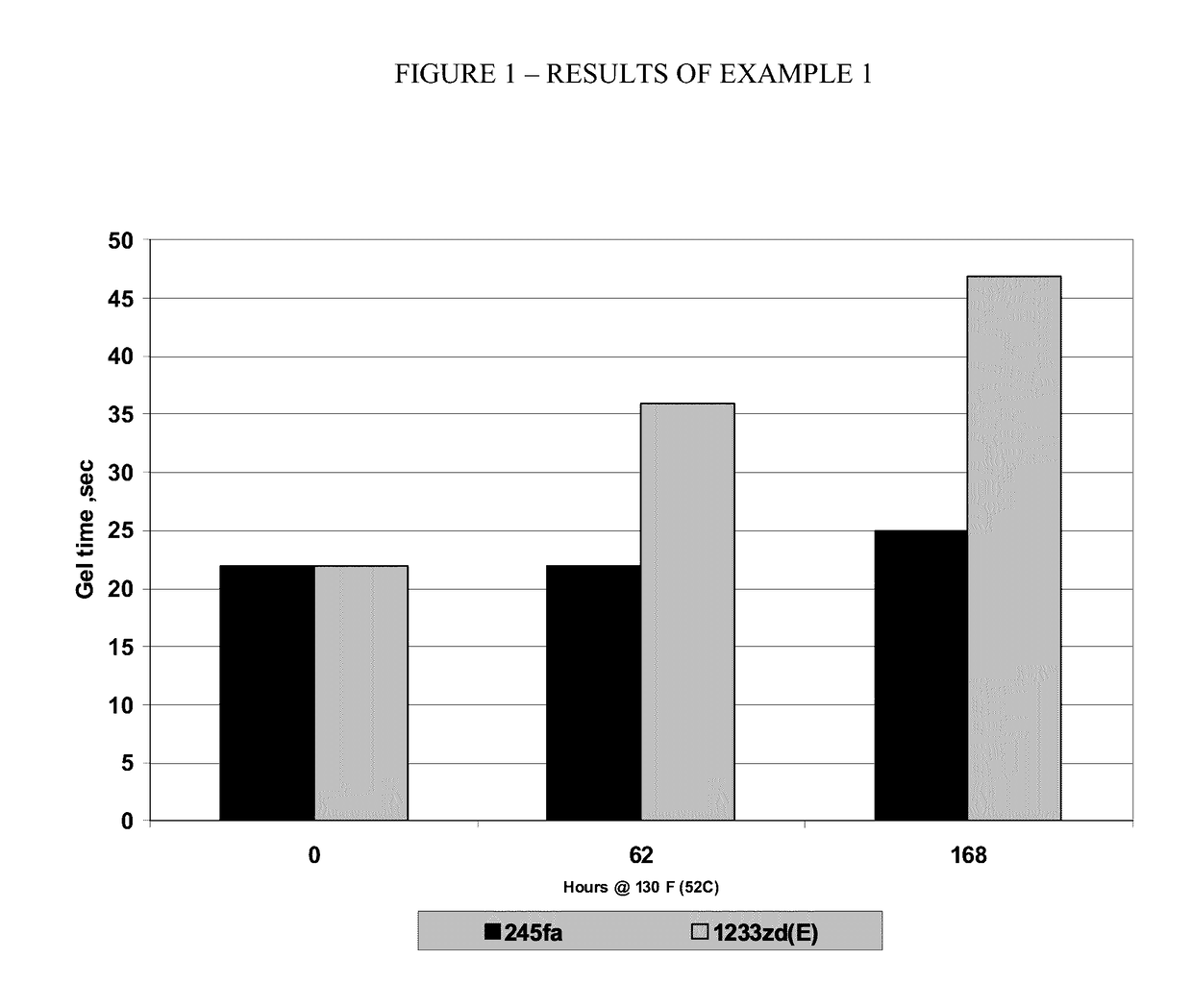
[0067]Two typical commercial polyol spray-foam formulations are formed in accordance with Table E1A below:

TABLE E1APolyol Blend, 50° F. (10° C.)245fa1233zd(E)ComponentsphpphpMannich polyether polyol having an OH# 470 4040(Veranol 470X)Aromatic polyester polyol (Terate 4020)6060Silicone surfactant (Dabco DC193)2.02.0Potassium octoate solution-15% in diethylene 1.41.4glycol (Dabco K-15)Polycat 5 (pentamethyldiethylene-triamine)1.41.4Dabco 33LV (Diazabicyclooctane 0.70.7(triethylenediamine)TCPP (tris (2-chloroisopropyl) phosphate 2020(Antiblaze TMCP(AB80))Water22245fa2001233zd(E)020Isocyanate, 70° F. (21° C.)Polymethyldiisocyanate (PMDI) (Lupranate M20S)ISO ISO Index =Index =150150

[0068]The formulations are maintained for up to 168 hours at about 52 C. Three different foams are formed from each formulation: one essentially upon initial formulation; one after about 62 hours of aging; and one after 168 hours of aging. Gel time is observed for each of the foams thus formed and ...

example 2

Spray Foam without Catalyst

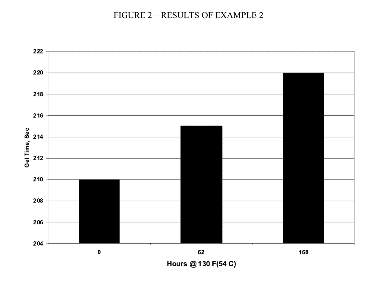
[0070]A typical commercial polyol spray-foam formulations, except with no catalyst present, is formed in accordance with Table E2 below.

TABLE E2Polyol Blend, 50° F. (10° C.)ComponentsphpVoranol ® 470X40Terate 4020 ®60Dabco ® DC1932Water2Antiblaze ® AB80201233zd(E)20Isocyanate, 70° F. (21° C.)Lupranate ® M20SISO Index = 150

After testing for stability, the results are as indicated FIG. 2.

[0071]The results reported above and illustrated in FIG. 2 indicate that 1233zd(E) is acceptable as a blowing agent for use in combination with typical commercially used polyol compounds, including particularly polyol compounds used in typical commercial spray foam applications without catalyst.

example 3a

Spray Foam with Catalyst

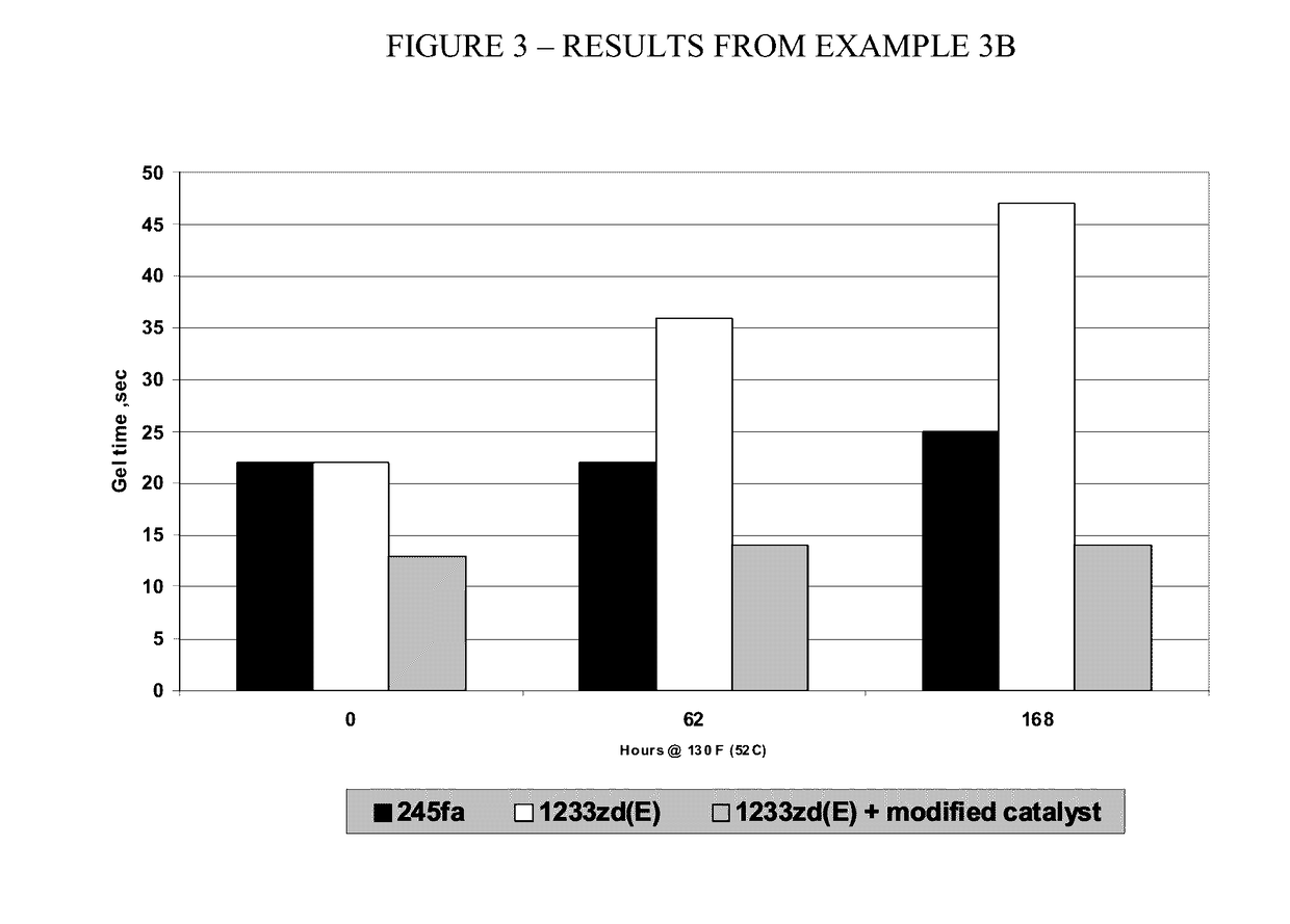
[0072]A polyol spray-foam formulation according to the present invention is formed using the preferred blowing agent 1233zd(E) but with a less-preferred catalyst system consisting of a single bismuth metal catalyst and a non-preferred amine-based catalyst in accordance with Table E3A below:

TABLE E3APolyol Blend, 50° F. (10° C.)ComponentsPhpVoranol ® 9 470X 40.0(Mannich polyether polyol)Terate ® 10 4020 60.0(Aromatic polyester polyol)Dabco ® 1 DC193 2.0(Silicone surfactant)Dabco K-151.4Polycat 51.4MB-20 Bismuth Catalyst0.7Antiblaze ® 13 AB8020Water21233zd20Isocyanate, 70° F. (21° C.)Lupranate ® 3 M20SIso Index = 150

[0073]Acceptabe results are obtained.


PUM

PropertyMeasurementUnit
Ozone Depletion Potentialaaaaaaaaaa
formulationaaaaaaaaaa

Abstract

The invention provides polyurethane and polyisocyanurate foams and methods for the preparation thereof. More particularly, the invention relates to closed-celled, polyurethane and polyisocyanurate foams and methods for their preparation. The foams are characterized by a fine uniform cell structure and little or no foam collapse. The foams are produced with a polyol premix composition which comprises a combination of a hydrohaloolefin blowing agent, a polyol, a silicone surfactant, and a non-amine catalyst used alone or in combination with an amine catalyst.

Description

CROSS REFERENCE TO RELATED APPLICATIONS[0001]The present application is a division of U.S. application Ser. No. 13 / 400,563, filed Feb. 20, 2012, which application relates to and claims the priority benefit of each of U.S. Application 61 / 445,027, filed Feb. 21, 2011 and U.S. Application 61 / 445,022, filed Feb. 21, 2011, each of which is incorporated herein by reference in its entirety as if fully set forth below.[0002]Also incorporated herein by reference is U.S. application Ser. No. 13 / 400,559, now U.S. Pat. No. 9,051,442.FIELD OF THE INVENTION[0003]The present invention pertains to polyurethane and polyisocyanurate foams, to blowing agents and catalyst systems and methods for the preparation thereof.BACKGROUND OF THE INVENTION[0004]Low density, rigid to semi-rigid polyurethane or polyisocyanurate foams have utility in a wide variety of insulation applications including roofing systems, building panels, building envelope insulation, spray applied foams, one and two component froth fo...

Claims


Application Information

Patent Timeline
Patent Type & Authority Applications(United States)
IPC IPC(8): C08G18/16C08G18/40C08G18/50C08J9/12C08J9/14C08G18/08C08G18/76
CPCC08G18/163C08G18/14C08G18/4018C08G18/7664C08J9/127C08J2375/08C08J9/125C08G18/5021C08J2203/182C08J2203/10C08J2203/162C08J9/144C08G18/1808C08G18/2063C08G18/225C08G18/227C08G18/26C08G18/4208C08G18/4804C08G18/4837C08G2101/00C08J9/146C08J2205/052C08J2375/04C08G18/092C08G18/1816C08G18/2081C08G18/244C08G18/546C08G2410/00C08G2110/0033C08G2115/02
Inventor ROSS, MICHAEL A.GROSSMAN, RONALDWILLIAMS, DAVID J.GITTERE, CLIFFORD P.
Owner HONEYWELL INT INC
Learn More