Power transmission apparatus

a technology of transmission apparatus and lubricating oil, which is applied in the direction of couplings, vehicle sub-unit features, gearing, etc., can solve the problems of erroneous engagement or deterioration of the duration life of the sowc, and the inability to intentionally control the supply amount of lubricating oil to a particular component, so as to achieve the effect of increasing the overlap area

Active Publication Date: 2017-03-09
TOYOTA JIDOSHA KK +1
View PDF3 Cites 12 Cited by
  • Summary
  • Abstract
  • Description
  • Claims
  • Application Information

AI Technical Summary

Benefits of technology

[0017]According to the power transmission apparatus of this embodiment, each of the sectional shape of the oil passage and the shape of the through-hole is formed in a rectangular shape, thereby more rapidly increasing an overlapping area between the through-hole and the opening of the oil passage in the engagement state of the selectable one-way clutch at the beginning of the overlapping of the through-hole with the opening of the oil passage, compared with forming the sectional shape of the oil passage and the shape of the through-hole into another shape (such as a circular shape) with the same area, therefore, it is possible to allow more of the lubricating oil to flow in with a smaller overlapping range.
[0018]According to the power transmission apparatus of the above embodiment, by bringing the through-hole formed in the selector plate to be in communication with or out of communication with the oil passage, it is possible to control the supply amount of the lubricating oil supplied into the selectable one-way clutch.

Problems solved by technology

Hence, it is impossible to intentionally control supply amount of the lubricating oil to a particular component, specifically, an SOWC.
Consequently, depending on the operation condition of the SOWC, deficiency and excess of the lubricating oil occurs inside the SOWC, which might cause, e.g., an erroneous engagement or deterioration of duration life of the SOWC.

Method used


Image

  • Power transmission apparatus
  • Power transmission apparatus
  • Power transmission apparatus

Examples


first embodiment

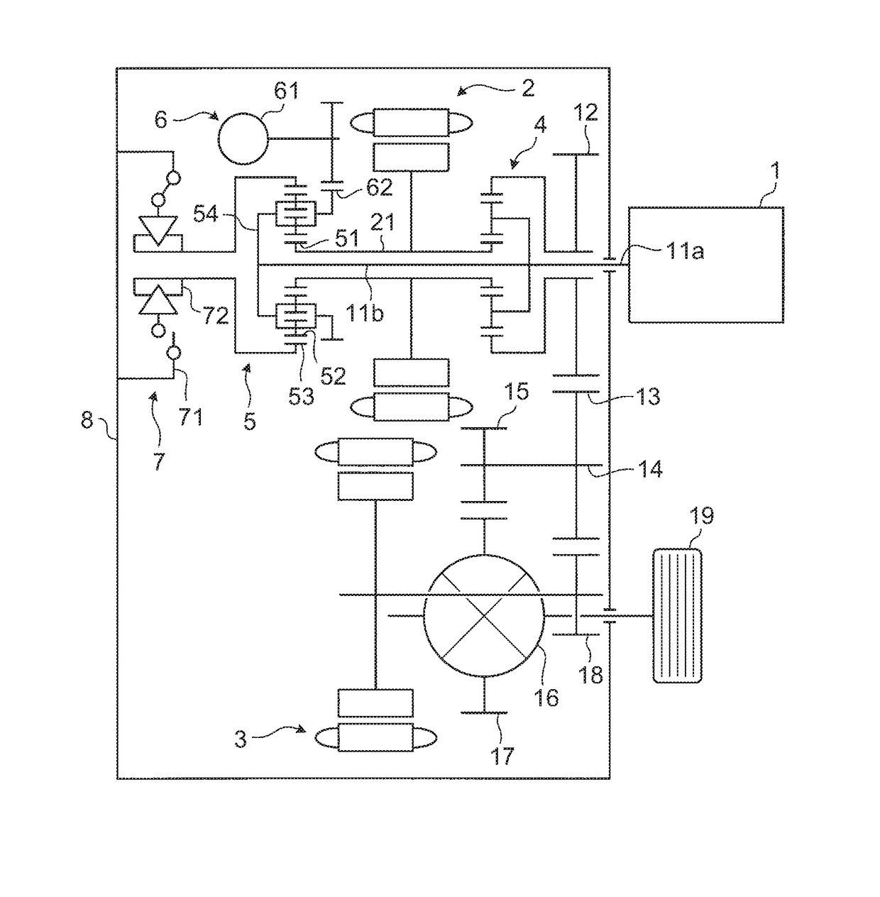
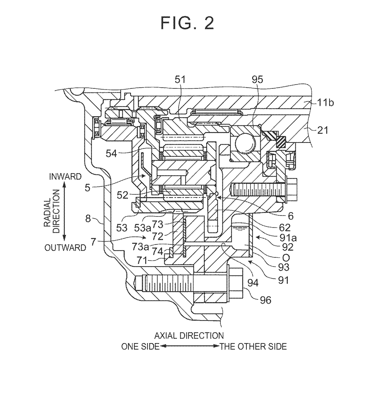
[0038]A vehicle equipped with a power transmission apparatus according to a first embodiment is a hybrid vehicle (HV vehicle) or a plug-in hybrid vehicle (PHV vehicle) including an engine and a motor as a driving power source, and more specifically, a split type (power split type) vehicle using an SOWC as a lock mechanism. The vehicle equipped with the power transmission apparatus according to the present embodiment includes an engine 1, a first rotary machine (motor) 2, a second rotary machine (motor) 3, a single pinion type planetary gear mechanism 4 that is a first differential mechanism, a double pinion type planetary gear mechanism 5 that is a second differential mechanism, an oil pump 6, an SOWC 7, a rear case 8 that is a housing case, and a center support 91 (see FIG. 2).

[0039]The vehicle equipped with the power transmission apparatus of the present embodiment includes: an input shaft 11b that is connected to an output shaft 11a of the engine 1 so as to receive power inputted...

embodiment example 1

[0074]As shown in FIG. 3A and FIG. 3B, the through-hole 73a according to Embodiment Example 1 is so formed as to extend through the selector plate 73 in the axial direction of the input shaft 11b, that is, in a thickness direction of the selector plate 73 (see FIG. 2). As shown in FIG. 3A and FIG. 3B, in the selector plate 73, the through-hole 73a is formed at a position where the through-hole 73a is not lined up with the opening of the oil passage 94 in the radial direction and the circumferential direction of the selector plate 73 in the non-engagement state of the SOWC 7, and the through-hole 73a is lined up with the opening of the oil passage 94 in the radial direction and the circumferential direction of the selector plate 73 in the engagement state of the SOWC 7. In other words, in the non-engagement state of the SOWC 7, the through-hole 73a is out of communication with the opening of the oil passage 94 in the axial direction of the input shaft 11b, and in the engagement state...

embodiment example 2

[0080]A through-hole 73Aa according to Embodiment Example 2 has the same function and the same area as those of the through-hole 73a according to Embodiment Example 1, but has a difference in shape from Embodiment Example 1. As shown in FIG. 5A and FIG. 5B, in the non-engagement state of an SOWC 7A, the through-hole 73Aa is not lined up with an opening of an oil passage 94A, and thus the supply amount of the lubricating oil O from the lubricating oil reservoir 92 side toward the SOWC 7A side becomes decreased. As shown in FIG. 6A and FIG. 6B, in the engagement state of the SOWC 7A, the through-hole 73Aa is lined up with the opening of the oil passage 94A, and thus the supply amount of the lubricating oil O from the lubricating oil reservoir 92 side toward the SOWC 7A side becomes increased.

[0081]As shown in FIG. 5A, the through-hole 73Aa is formed at an outer peripheral position in a selector plate 73A, that is, a position in the selector plate 73A on a bottom side of the lubricatin...


PUM


Abstract

A power transmission apparatus includes: an input shaft; a selectable one-way clutch; a housing case; a center support; a lubricating oil reservoir; and an oil passage. The oil passage extends through a pocket plate disposed between the lubricating oil reservoir and a selector plate. The selector plate includes a through-hole. The through-hole is located at a position where the through-hole is not lined up with the opening of the oil passage in a radial direction and a circumferential direction of the selector plate in a non-engagement state of the selectable one-way clutch, and also at a position where the through-hole is lined up with the opening of the oil passage in the radial direction and the circumferential direction of the selector plate in an engagement state of the selectable one-way clutch.

Description

INCORPORATION BY REFERENCE[0001]The disclosure of Japanese Patent Application No. 2015-176751 filed on Sep. 8, 2015 including the specification, drawings and abstract is incorporated herein by reference in its entirety.BACKGROUND OF THE INVENTION[0002]1. Field of the Invention[0003]Embodiments of the present invention relate to a power transmission apparatus.[0004]2. Description of Related Art[0005]There have been known hybrid vehicles (HV vehicles) equipped with engines and motors as driving power sources, and capable of carrying out the EV drive using only the motors while the engines are stopped. For example, Japanese Patent Application Publication No. 2015-77846 discloses a power transmission apparatus of a hybrid vehicle including a selectable one-way clutch (hereinafter, referred to as an SOWC) as a lock mechanism in a housing case (rear case). This power transmission apparatus supplies a lubricating oil into the SOWC by a mechanical oil pump driven by an engine power.SUMMARY[...

Claims


Application Information

Patent Timeline
Patent Type & Authority Applications(United States)
IPC IPC(8): B60K6/383B60K6/46F16H3/72F16D41/18F16H57/021F16H57/04
CPCB60K6/383F16H57/021F16H57/0436F16H57/045F16H57/0484F16H57/042B60Y2400/427F16H3/727F16D41/18B60K6/46Y10S903/913F16D2300/06B60Y2200/92F16H57/0483B60K6/36B60K6/365B60K6/445F16D41/02F16D41/14F16H3/724F16H57/0424F16H57/0434F16H57/0473F16H57/0476Y02T10/62B60K6/387B60K6/405F16D41/08F16D41/125
Inventor KUROSAKI, YUKISHIOIRI, HIROYUKISHIBATA, HIROYUKIYASUI, HIROKI
Owner TOYOTA JIDOSHA KK
Why Eureka
Try Eureka