
Multi-level image focus using a tunable lens in a machine vision inspection system

a machine vision inspection and multi-level technology, applied in the field of precision metrology, can solve the problems of mechanical complexity, method is also relatively slow, and method is also relatively slow, and achieve the effect of improving overall image focus

Active Publication Date: 2017-03-02
MITUTOYO CORP
View PDF0 Cites 44 Cited by
  • Summary
  • Abstract
  • Description
  • Claims
  • Application Information

AI Technical Summary

Benefits of technology

The patent describes a method for improving the acquisition of a multi-exposure image in a machine vision inspection system. The method involves defining regions of interest on a workpiece and using strobed illumination to capture images at different focus positions. The recorded data is then used to control the acquisition of the multi-exposure image of the workpiece during a run mode. The technical effect of this method is to enhance overall image focus for the regions of interest while acquiring a multi-exposure image of the workpiece.

Problems solved by technology

However, this method is relatively slow.
This method is also relatively slow and mechanically complex.

Method used


Image

  • Multi-level image focus using a tunable lens in a machine vision inspection system
  • Multi-level image focus using a tunable lens in a machine vision inspection system
  • Multi-level image focus using a tunable lens in a machine vision inspection system

Examples


Embodiment Construction

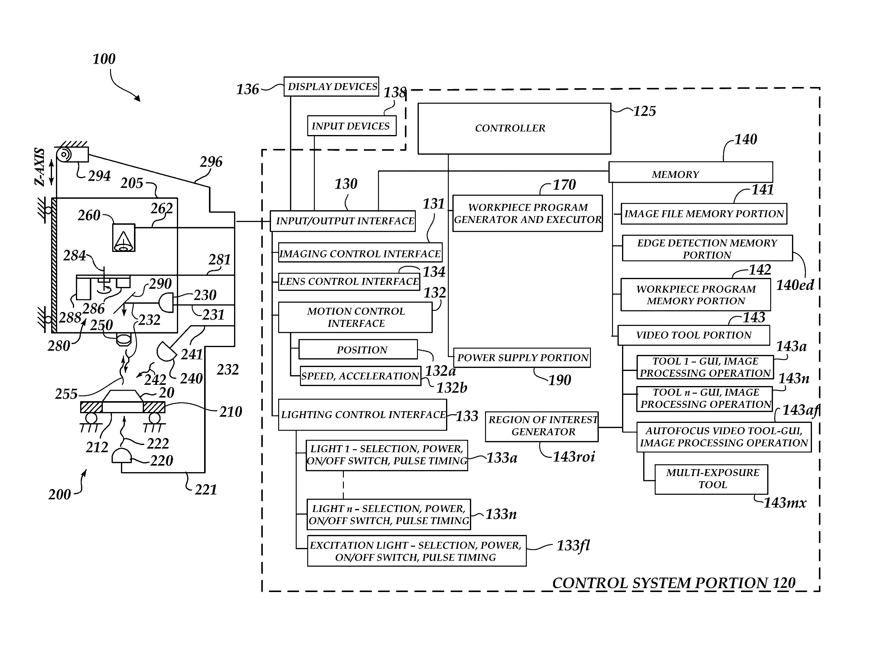
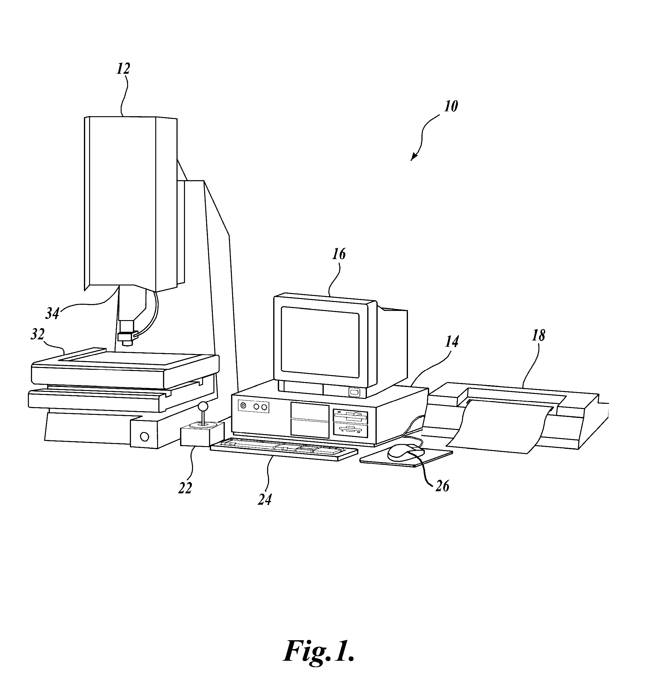
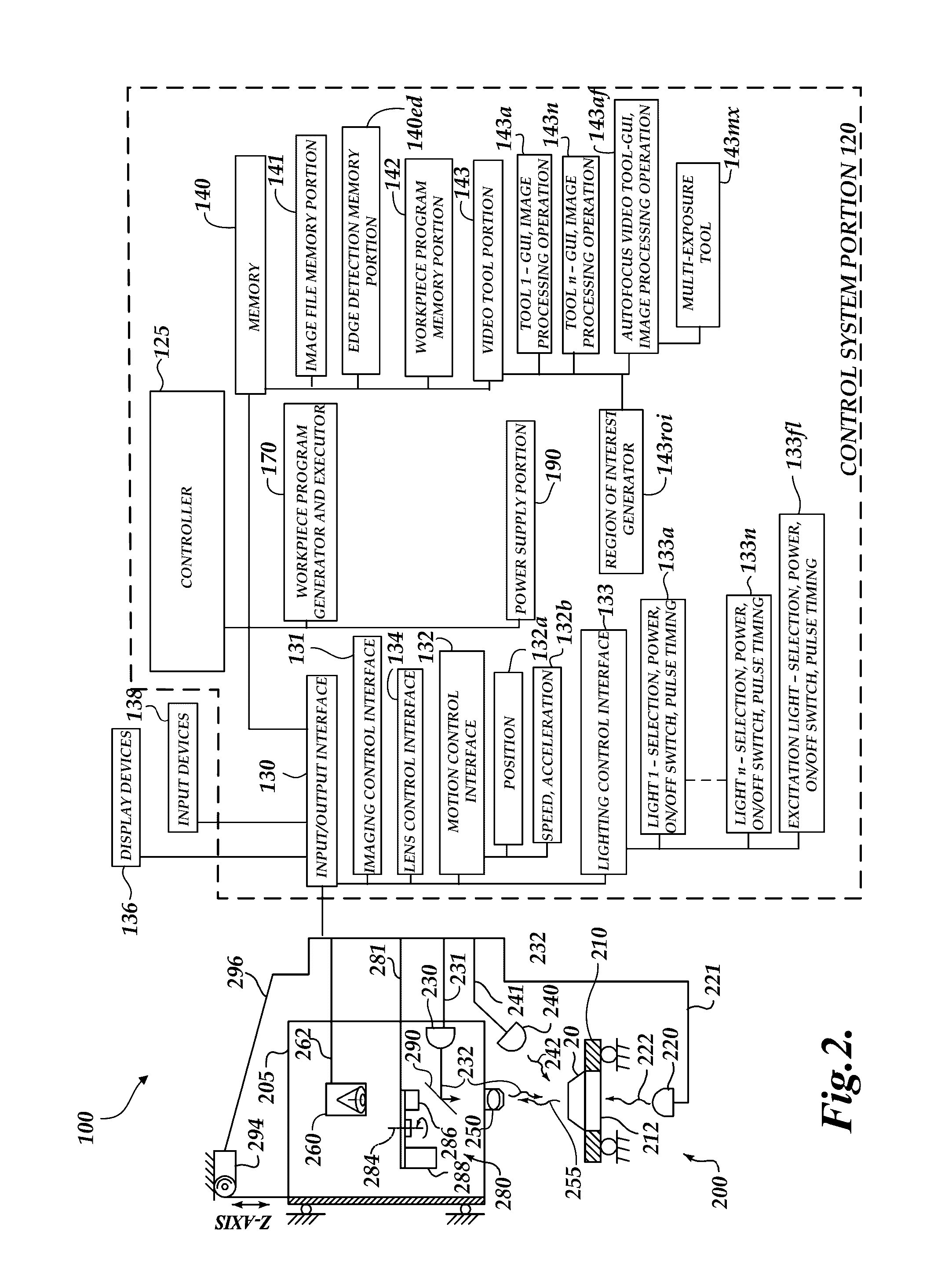
[0023]FIG. 1 is a block diagram of one exemplary machine vision inspection system 10 usable in accordance with principles disclosed herein. The machine vision inspection system 10 includes a vision measuring machine 12 that is operably connected to exchange data and control signals with a controlling computer system 14, and with a monitor or display 16, a printer 18, a joystick 22, a keyboard 24, and a mouse 26. The monitor or display 16 may display a user interface suitable for controlling and / or programming the machine vision inspection system 10. In various implementations, a touchscreen tablet or the like may be substituted for and / or redundantly provide the functions of any or all of the computer system 14, display 16, joystick 22, keyboard 24, and mouse 26.

[0024]More generally, the controlling computer system 14 may comprise or consist of any computing system or device, and / or distributed computing environment, and the like, any of which may include one or more processors that...


PUM

PropertyMeasurementUnit
frequencyaaaaaaaaaa
frequencyaaaaaaaaaa
focal lengthaaaaaaaaaa

Abstract

A method is provided for defining operations for acquiring a multi-exposure image of a workpiece including first and second regions of interest at different Z heights. The multi-exposure image is acquired by a machine vision inspection system including strobed illumination and a variable focal length lens (e.g., a tunable acoustic gradient index of refraction lens) used for periodically modulating a focus position. During a learn mode, first and second multi-exposure timing values for instances of strobed illumination are determined that correspond with first and second phase timings of the periodically modulated focus position that produce sufficient image focus for the first and second regions of interest. Data indicative of the multi-exposure timing difference is recorded and is subsequently utilized (e.g., during a run mode) to define operations for acquiring a multi-exposure image of first and second regions of interest on a current workpiece that is similar to the representative workpiece.

Description

BACKGROUND[0001]Technical Field[0002]This disclosure relates to precision metrology, and more particularly to machine vision inspection systems in which a variable focal length lens may be utilized to periodically modulate a focus position.[0003]Description of the Related Art[0004]Precision machine vision inspection systems (or “vision systems” for short) may be used for precise measurements of objects and to inspect other object characteristics. Such systems may include a computer, camera, optical system, and a stage that moves to allow workpiece traversal. One exemplary system, characterized as a general-purpose “off-line” precision vision system, is the QUICK VISION® series of PC-based vision systems and QVPAK® software available from Mitutoyo America Corporation (MAC), located in Aurora, Ill. The features and operation of the QUICK VISION® series of vision systems and the QVPAK® software are generally described, for example, in the QVPAK 3D CNC Vision Measuring Machine User's Gu...

Claims


Application Information

Patent Timeline
Patent Type & Authority Applications(United States)
IPC IPC(8): G06T7/00G02F1/33G06K9/66H04N5/232H04N5/235H04N5/225G02B3/00G06F3/0484G06V10/145G06V10/147G06V30/194
CPCG06T7/0004G02B3/0081G02F1/33G02B3/0087G06T7/0081G06T7/0085G06T2207/30164H04N5/23212H04N5/2353H04N5/2256G06K9/66G02F2001/294G06F3/04842G01B11/00H04N23/673H04N23/632G02B21/0016G02B21/0084G02B21/367G06T5/50G06T2207/10148G02F1/294G06V10/145G06V10/147G06V30/194H04N23/56H04N23/743H04N23/73H04N23/74G06T5/73
Inventor BRYLL, ROBERT KAMIL
Owner MITUTOYO CORP
Learn More