Method and apparatus for producing a thin glass ribbon, and thin glass ribbon produced according to such method
a technology of thin glass ribbon and thin glass, which is applied in the direction of glass forming apparatus, glass making apparatus, manufacturing tools, etc., can solve the problems of uncontrolled glass breakage and slow cooling of the border, and achieve the effects of reducing thickness, reducing friction, and reducing friction
- Summary
- Abstract
- Description
- Claims
- Application Information
AI Technical Summary
Benefits of technology
Problems solved by technology
Method used
Image

Examples
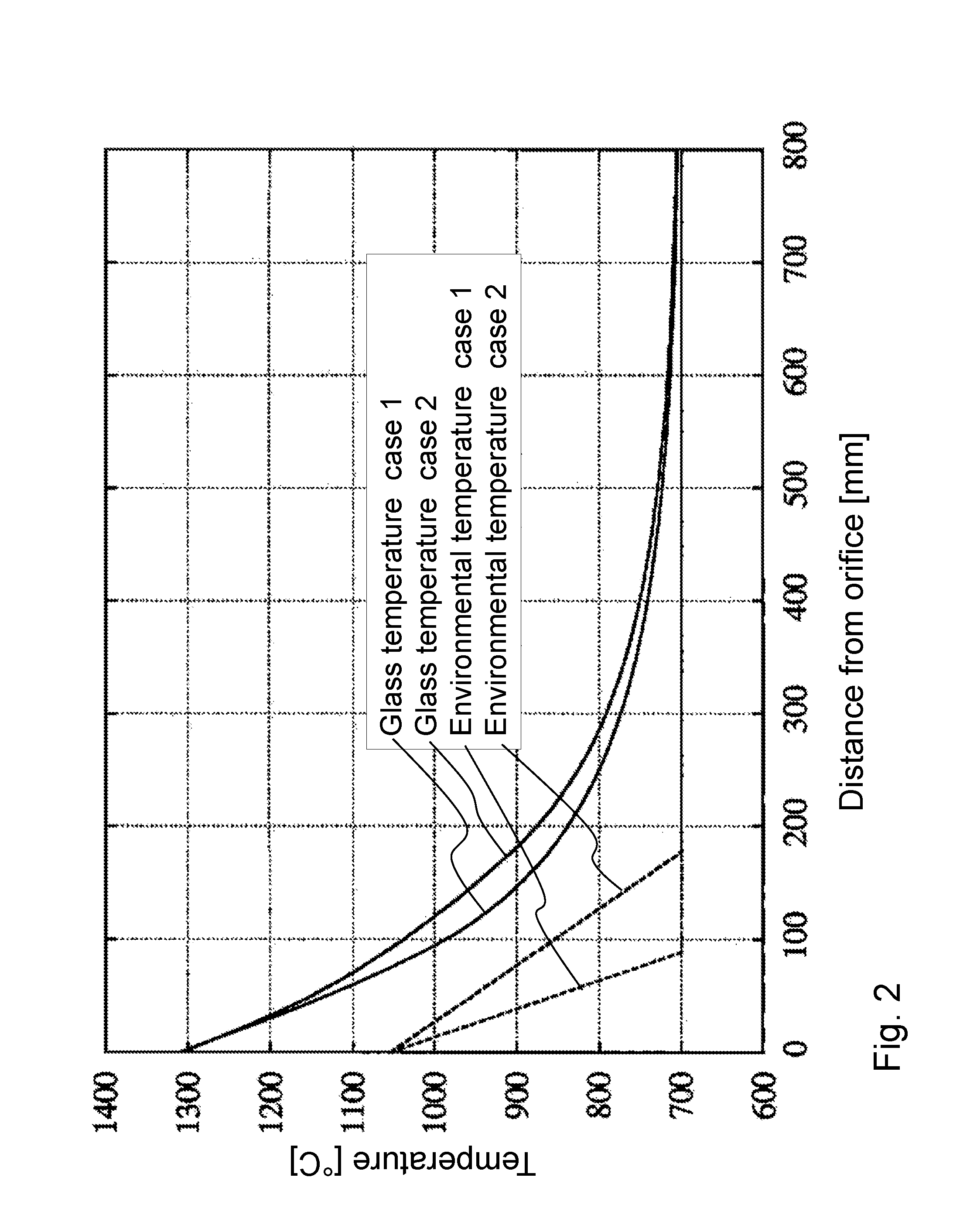
case 1 (
[0107with a temperature gradient of 4000 K / m): T(y)=max (700° C.; 1055° C.)+4000*y; and
case 2 (
[0108with a temperature gradient of 2000 K / m): T(y)=max (700° C.; 1055° C.)+2000*y.
[0109]Here, y denotes the distance to the drawing orifice in meters. The resulting glass temperatures for the thin glass ribbon having a thickness of 50 μm and for the thin glass ribbon having a thickness of 100 μm are virtually identical.
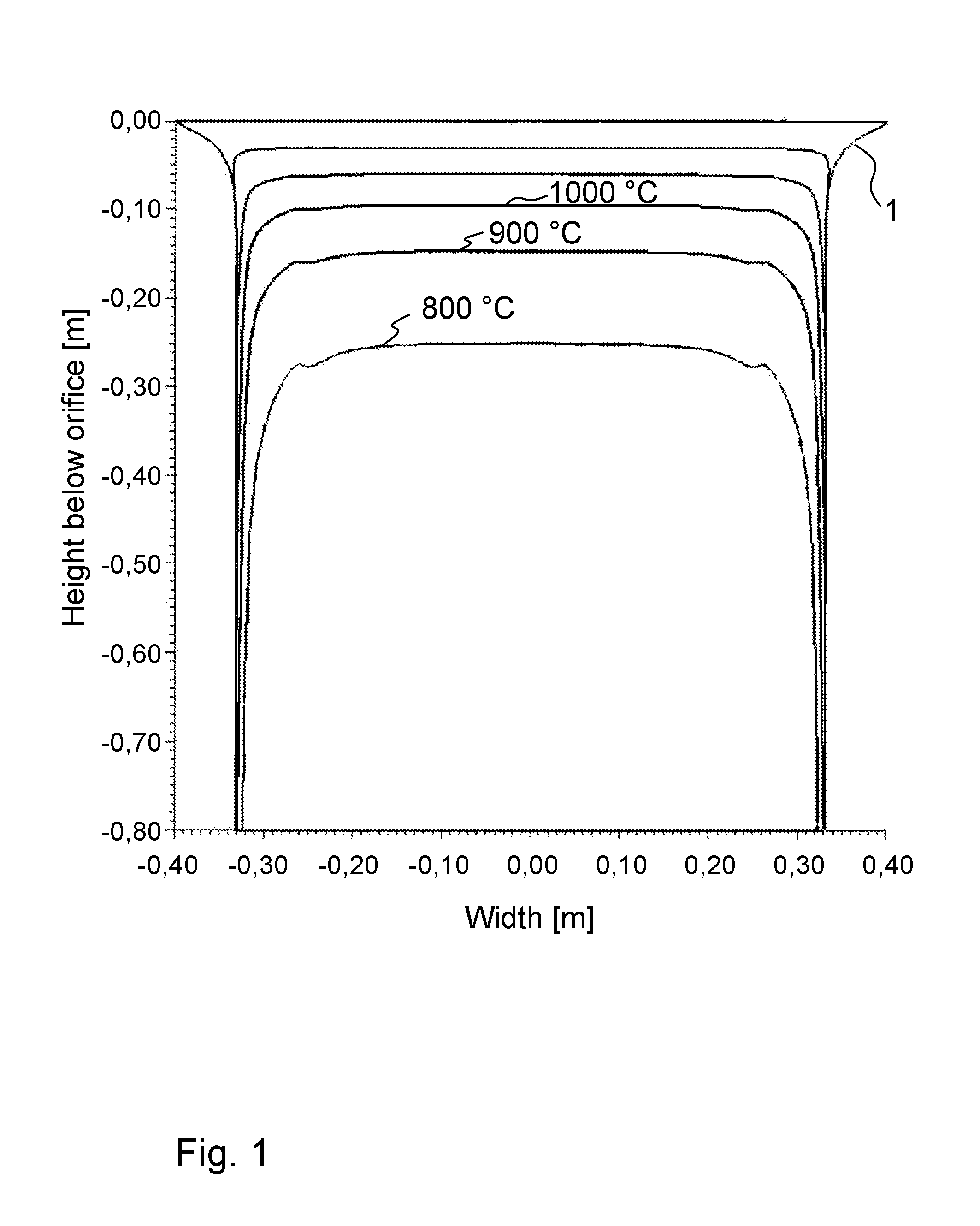
[0110]FIGS. 3 to 8 each show diagrams with a thickness of the glass ribbon of 100 μm, with FIG. 3 to FIG. 5 given for case 1, and FIG. 6 to FIG. 8 given for case 2.
[0111]FIG. 3 and FIG. 6 each show a diagram of temperature profiles at different heights of 50 mm, 100 mm, 200 mm, 300 mm, and 400 mm below the orifice as a function of the width of the glass ribbon, for case 1 and case 2, respectively, with a thickness of the glass ribbon of 100 μm in each case.
[0112]As can be seen therefrom, up to approximately 400 mm below the orifice the temperature is still above the transformation temperature of the glass AF32® of 713° C. Therefore, the range with a distance of less ...
PUM
| Property | Measurement | Unit |
|---|---|---|
| thickness | aaaaa | aaaaa |
| viscosity | aaaaa | aaaaa |
| distance | aaaaa | aaaaa |
Abstract
Description
Claims
Application Information
 - R&D
- Intellectual Property
- Life Sciences
- Materials
- Tech Scout
- Unparalleled Data Quality
- Higher Quality Content
- 60% Fewer Hallucinations
Browse by: Latest US Patents, China's latest patents, Technical Efficacy Thesaurus, Application Domain, Technology Topic, Popular Technical Reports.
© 2025 PatSnap. All rights reserved.Legal|Privacy policy|Modern Slavery Act Transparency Statement|Sitemap|About US| Contact US: help@patsnap.com