Circuit board connector and circuit board

Inactive Publication Date: 2017-02-23
SUMITOMO WIRING SYST LTD
View PDF12 Cites 6 Cited by
  • Summary
  • Abstract
  • Description
  • Claims
  • Application Information

AI Technical Summary

Benefits of technology

This patent is related to improving the overall operability and preventing interference between adjacent terminals in a circuit board connector. The patent suggests using an inclined portion on the rear end of the receiving portion of the terminal to guide the tool used to push the terminal into the circuit board. This prevents the tool from slipping and ensures reliable pushing of the terminal. The receiving portions on the outer edge parts of adjacent terminals are positioned at different locations in the press-fitting direction to prevent interference and minimize the distance between the terminals. Additionally, the patent also suggests using a common shape near the receiving portions to further prevent interference. These technical measures enhance the overall performance and reliability of the circuit board connector.

Problems solved by technology

In such a configuration essentially including a plurality of types of terminals largely different in shape in this way, manufacturing burdens due to an increase in the number of types of terminals is unavoidable.

Method used


Image

  • Circuit board connector and circuit board
  • Circuit board connector and circuit board
  • Circuit board connector and circuit board

Examples


Embodiment Construction

[0026]Hereinafter, an embodiment is described with reference to FIGS. 1 to 5.

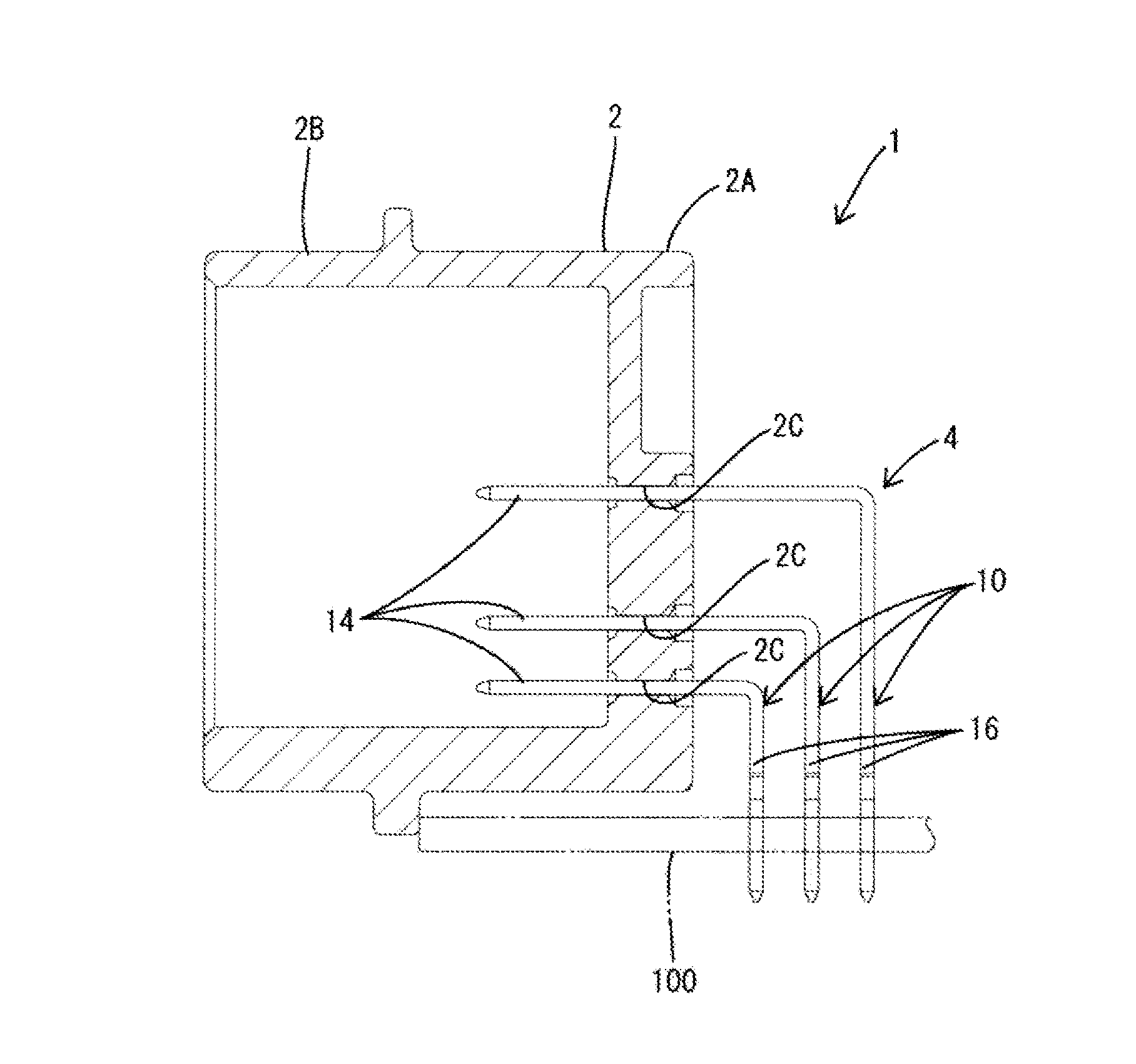
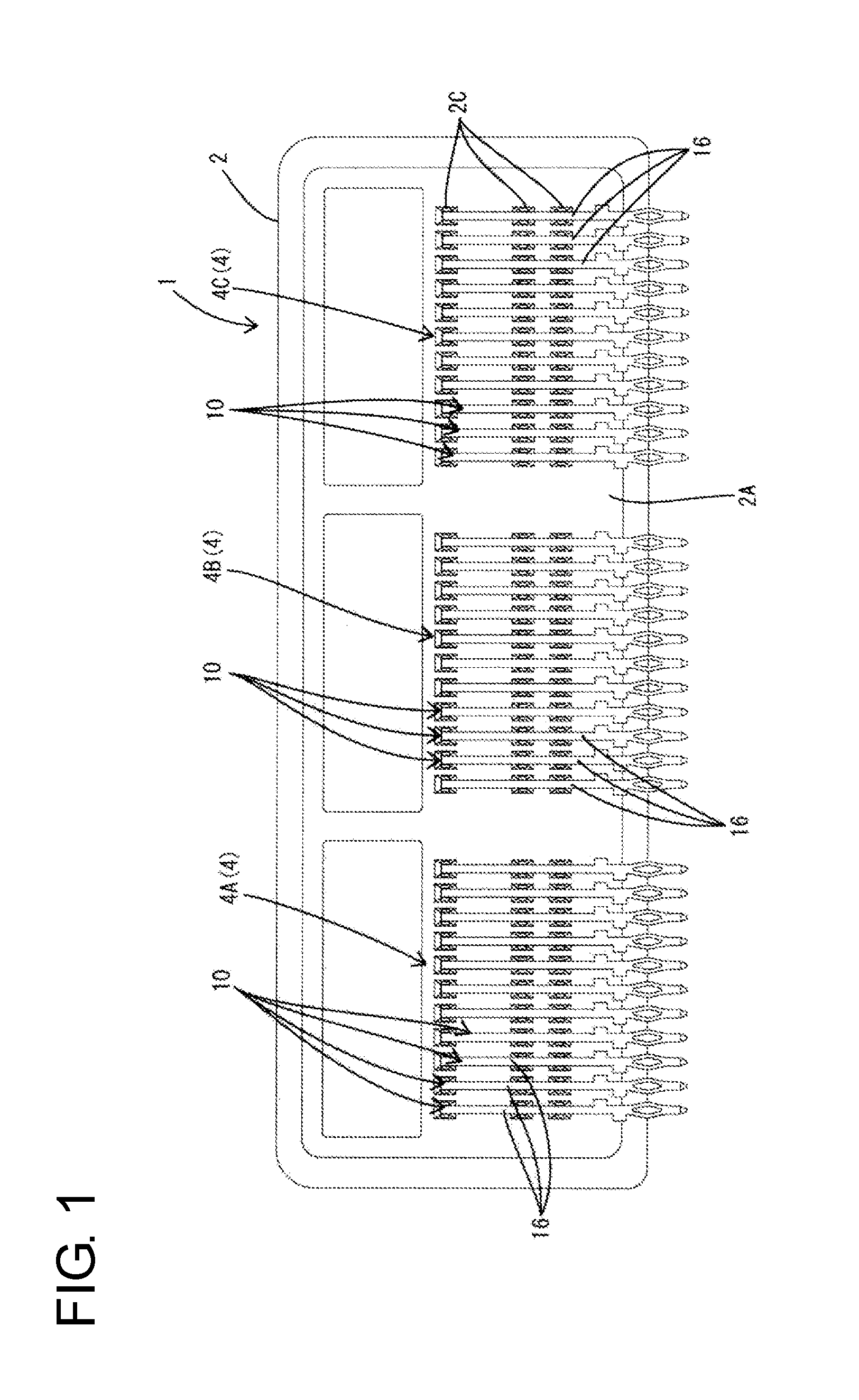
[0027]A circuit board connector 1 (hereinafter, also merely referred to as a connector 1) illustrated in FIGS. 1 to 5 is configured, for example, as a vehicle-mounted connector to be connected to a vehicle-mounted circuit board. As shown in FIGS. 1 and 2, this connector 1 mainly includes a housing 2 made of synthetic resin and a plurality of terminals 10 to be mounted by being at least partly inserted through or into the housing 2.

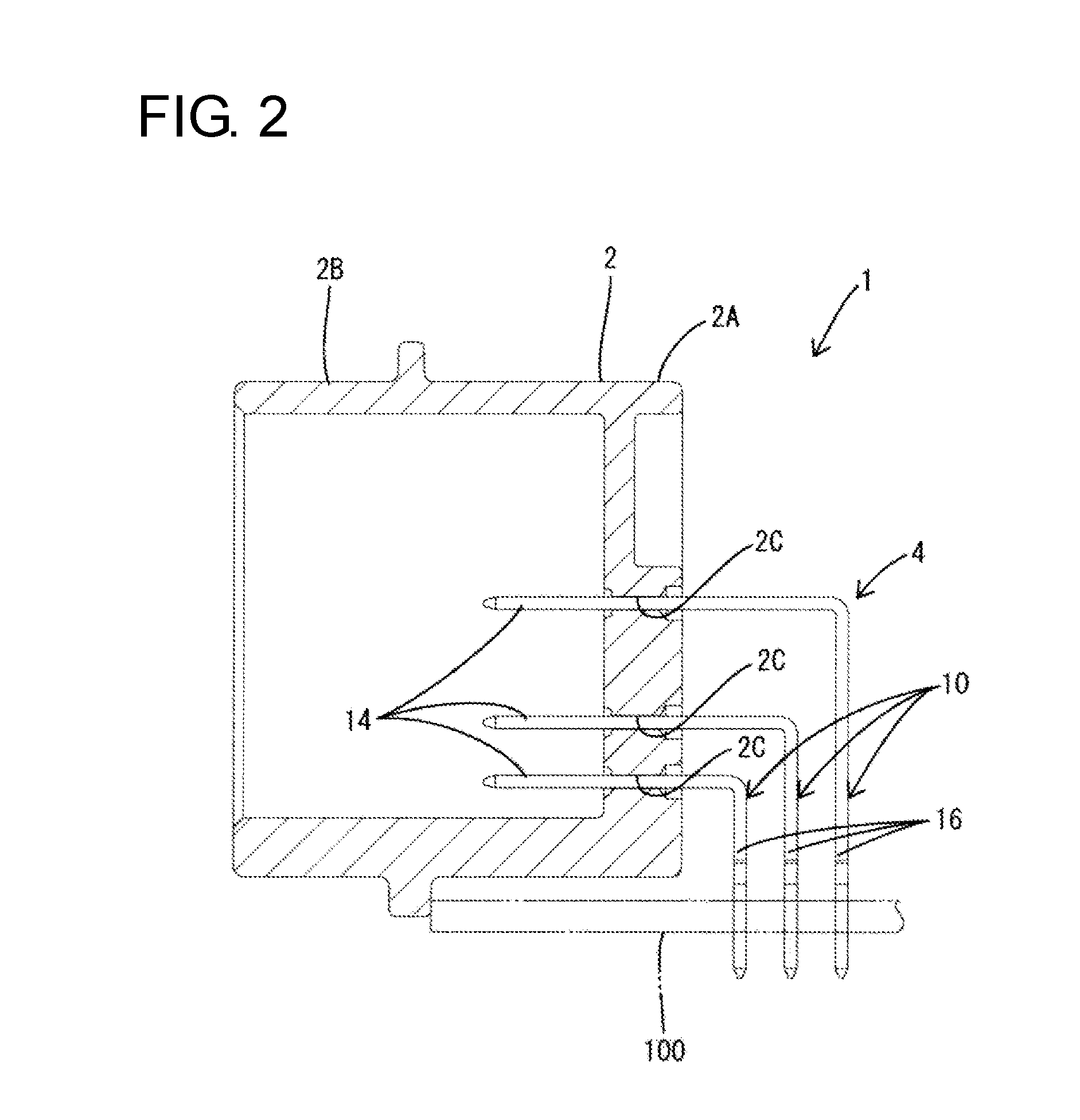
[0028]In the following description, a lateral direction of FIGS. 1, 3 and 4 is referred to as a lateral direction of the connector 1. Further, a vertical direction is based on FIGS. 1 to 4. Further, a lateral direction of FIG. 2 is referred to as a front-back direction and a mating side with a (unillustrated) mating connector (a left side of FIG. 2) is referred to as a front side of the connector 1.

[0029]The housing 2 has a main body portion 2A formed to be long in the lateral dir...


PUM


Abstract

A circuit board connector (1) includes terminal groups (4) in which a plurality of terminals (10) are arranged. A downward extending portion (16) of the terminal (10) constituting the terminal group (4) is formed with a press-fit portion (20) to be press-fit into a mounting hole (102) of a circuit board (100). Receiving portions (31, 32) projecting in a direction intersecting with a press-fitting direction are respectively formed on outer edge parts (12A, 12B) on opposite sides in an arrangement direction on a side behind the press-fit portion (20) in the press-fitting direction. The receiving portions of each terminal (10) are located at positions different in the press-fitting direction, and the receiving portions respectively formed on the outer edge parts facing each other are located at positions different in the press-fitting direction between adjacent terminals adjacent in the arrangement direction.

Description

BACKGROUND[0001]1. Field of the Invention[0002]The invention relates to a circuit board connector and a circuit board provided therewith.[0003]2. Description of the Related Art[0004]Japanese Unexamined Patent Publication No. 2004-178992 shows a conventionally available press-fit terminal to be inserted into a through hole formed on a circuit board and electrically connected to the circuit board by a resilient force. In this technique, the press-fit terminals provided side by side in a connector housing are coupled to the circuit board by a terminal press-fitting tool.[0005]In the case of press-fitting terminals of a press-fit structure into through holes formed on a circuit board, the terminals need to be pushed into while being pressed by a tool. In the technique of Japanese Unexamined Patent Publication No. 2004-178992, receiving portions protruding toward left and right sides of the terminal are provided and the terminal is pushed into the through hole by pushing the receiving po...

Claims


Application Information

Patent Timeline
IPC IPC(8): H01R12/70H01R12/71H01R13/405H01R43/048
CPCH01R12/7064H01R43/0484H01R13/405H01R12/716H01R12/7082H01R12/55H01R13/02H01R13/40H01R12/585H01R12/724
Inventor KIKUCHI, TAKAHIRO
Owner SUMITOMO WIRING SYST LTD
Why Eureka
Try Eureka