Aluminum Electrical Wire with Crimped Terminal and Method for Producing Aluminum Electrical Wire with Crimped Terminal
a technology of aluminum electrical wire and crimping terminal, which is applied in the direction of dustproof/splashproof/drip-proof/waterproof/flameproof connection, connection contact material, etc., can solve the problems of increasing the crimping terminal and the electrical conduction state, and achieve the effect of preventing electrolytic corrosion, preventing the electrolytic corrosion, and low cos
- Summary
- Abstract
- Description
- Claims
- Application Information
AI Technical Summary
Benefits of technology
Problems solved by technology
Method used
Image
Examples
example 1
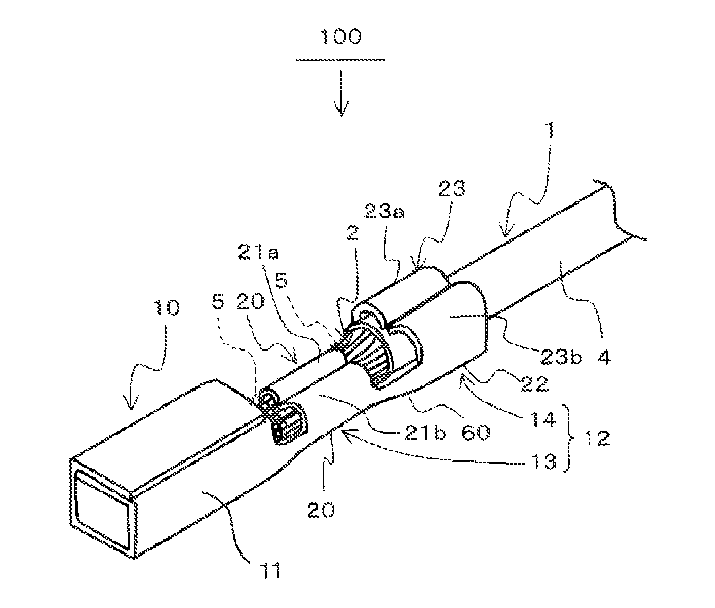
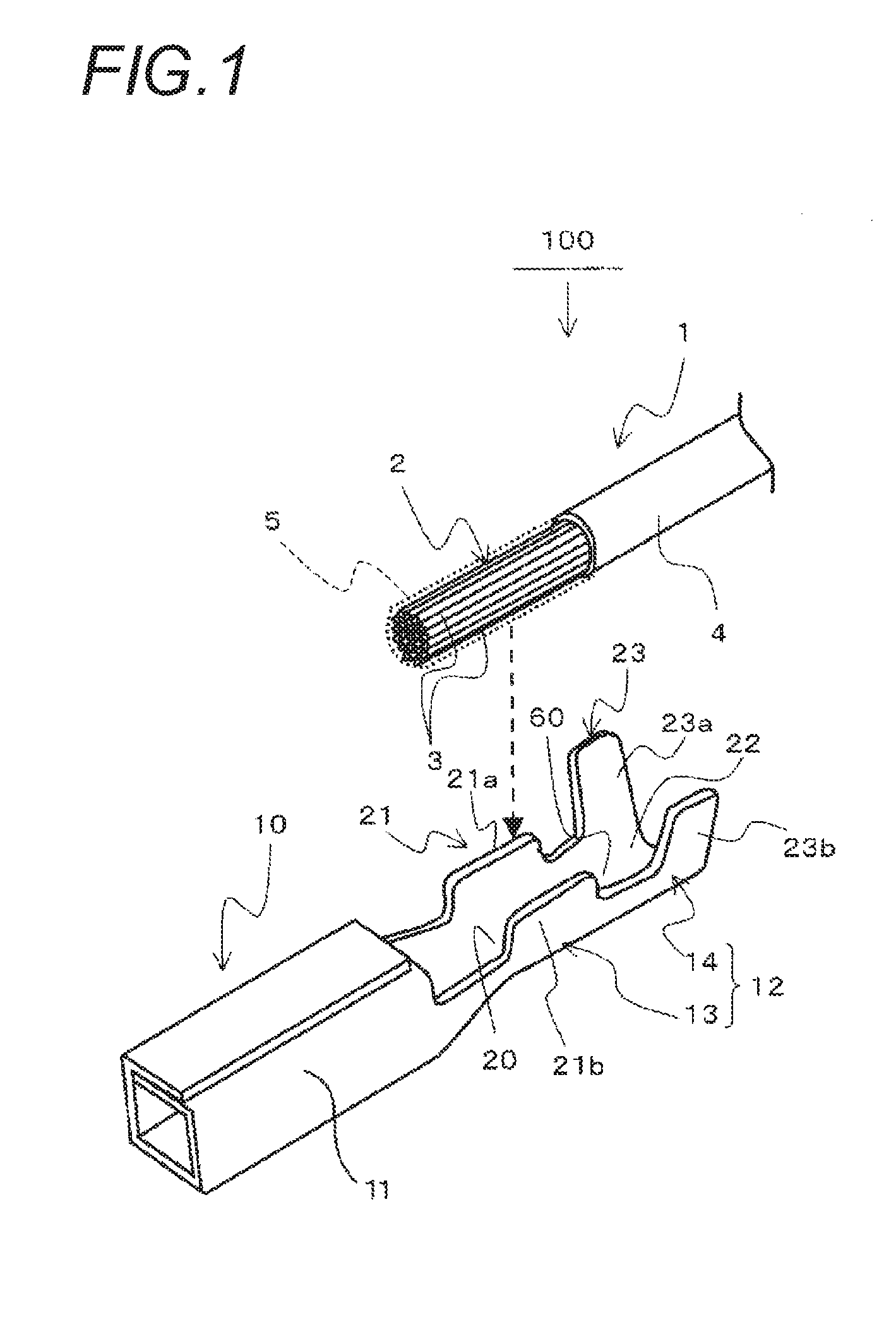
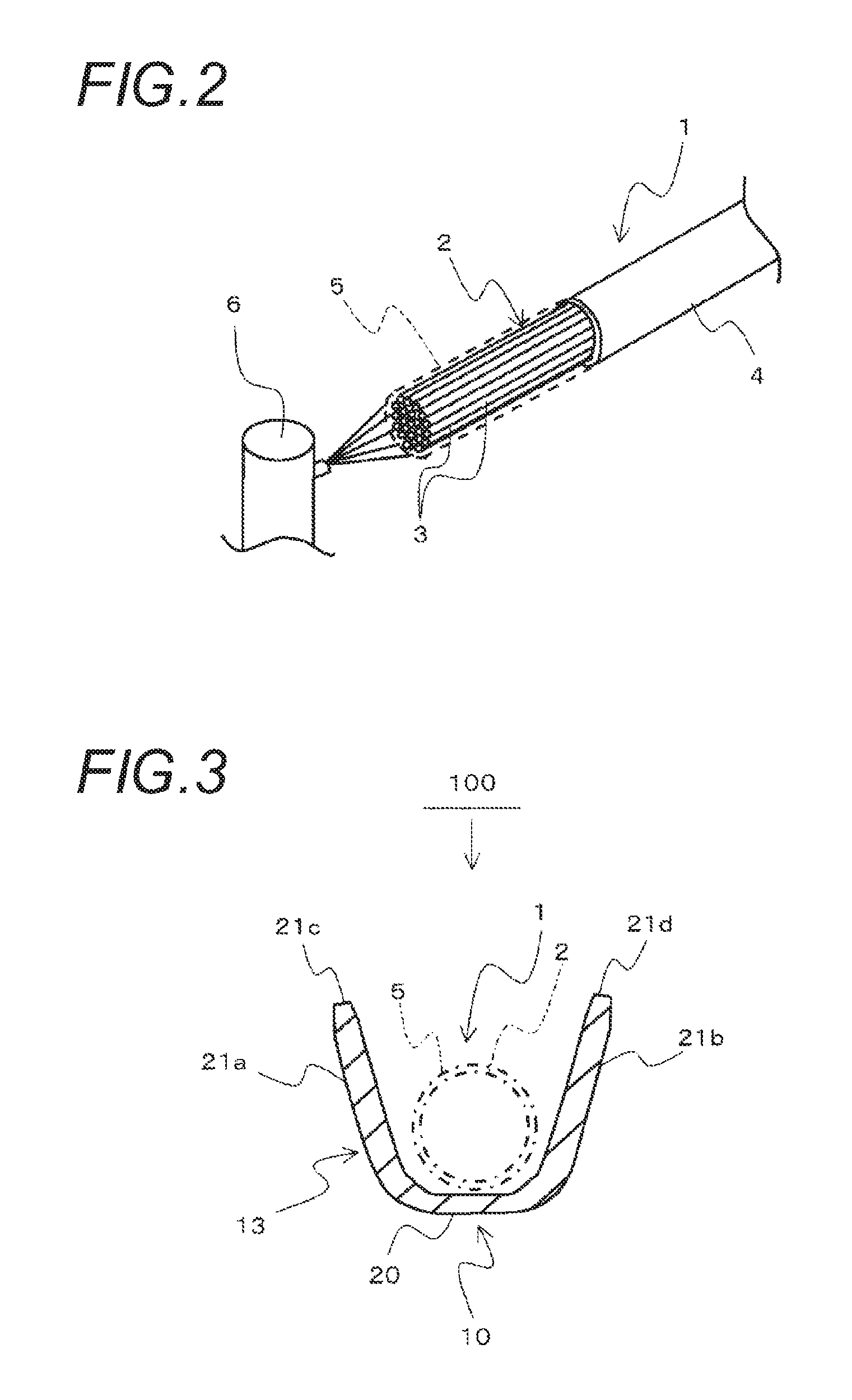
[0058]FIG. 1 is an exploded perspective view illustrating Example 1 of an aluminum cable with crimping terminal according to an embodiment of the present invention.
[0059]As shown in FIG. 1, an aluminum cable 1 includes a conductor 2 constituted by twisting a plurality of aluminum or aluminum alloy strands 3, and an outer periphery of the conductor 2 is covered with an insulating covering member 4.
[0060]Examples of the aluminum alloy that constitutes the aluminum cable 1 include an alloy of aluminum and iron. In comparison to an aluminum conductor, the alloy that is easily stretched can be further strengthened (particularly, tensile strength).
[0061]In addition, the insulating covering member 4 is peeled off from a terminal portion (front end of the cable) of the aluminum cable 1 with a predetermined length to expose the conductor 2, and a crimping terminal 10 is crimped to the terminal portion of the aluminum cable 1. A water-repellent agent 5 is applied to the conductor 2 over the e...
example 2
[0097]FIGS. 7A and 7B are exploded perspective views of an aluminum cable 200 with crimping terminal according to Example 2. FIG. 7A illustrates a state before a crimping terminal 40 is crimped to the aluminum cable 1, and FIG. 7B illustrates a state in which crimping of the crimping terminal 40 to the aluminum cable 1 is completed.
[0098]Example 2 illustrated in FIGS. 7A and 7B is different from Example 1 illustrated in FIG. 1 in a configuration of the crimping terminal 40, a configuration in which the water-repellent agent 5 applied to the conductor 2 of the aluminum cable 1 is applied to only the front end of the conductor 2 instead of the entirety of the outer periphery of the conductor 2, and a configuration in which a conductor crimping portion 43 and an insulating-cover crimping portion 44 of a cable crimping portion 42 are connected to each other.
[0099]The other configurations are the same as Example 1, and the same reference numerals are given to the same constituent portion...
example 3
[0113]FIG. 8 is a side view of an aluminum cable 300 with crimping terminal according to Example 3 of the present invention, and illustrates a state in which the water-repellent agent 5 is sprayed by a spraying sprayer 7.
[0114]Example 3 illustrated in FIG. 8 is different from Example 1 illustrated in FIG. 1 in the following ways. In Example 1 illustrated in FIG. 1, the water-repellent agent 5 is applied to the entirety of the outer periphery of the conductor 2 of the terminal portion (front end of the cable) of the aluminum cable 1 from which the insulating covering member 4 is removed. In contrast, in Example 3 illustrated in FIG. 8, with respect to the front end of the conductor 2 of the aluminum cable 1, and a portion of the exposed conductor 2 which is not covered with the conductor crimping portion 13 of the crimping terminal 10 and is exposed to outside air, the water-repellent agent 5 is sprayed by the spraying sprayer 7 to perform water-repellent treatment with the water-rep...
PUM
| Property | Measurement | Unit |
|---|---|---|
| weight | aaaaa | aaaaa |
| contact resistance | aaaaa | aaaaa |
| electrolytic corrosion | aaaaa | aaaaa |
Abstract
Description
Claims
Application Information
 - R&D
- Intellectual Property
- Life Sciences
- Materials
- Tech Scout
- Unparalleled Data Quality
- Higher Quality Content
- 60% Fewer Hallucinations
Browse by: Latest US Patents, China's latest patents, Technical Efficacy Thesaurus, Application Domain, Technology Topic, Popular Technical Reports.
© 2025 PatSnap. All rights reserved.Legal|Privacy policy|Modern Slavery Act Transparency Statement|Sitemap|About US| Contact US: help@patsnap.com


