
Acoustic module and control system for handheld ultrasound device

a handheld ultrasound and control system technology, applied in the field of ultrasonic devices, can solve the problems of affecting the acoustic field, negatively affecting the operation of the device, and difficult to keep bubbles from forming in water and other liquid mediums, so as to improve the overall acoustic uniformity and improve the acoustic outpu

Active Publication Date: 2017-02-16
ACCESS BUSINESS GRP INT LLC
View PDF10 Cites 20 Cited by
  • Summary
  • Abstract
  • Description
  • Claims
  • Application Information

AI Technical Summary

Benefits of technology

The present invention provides a solid waveguide for a handheld ultrasonic device that overcomes limitations of fluid-filled acoustic modules, such as bubbles and temperature sensitivity. The solid waveguide has curved surfaces that focus the acoustic energy and a contact surface that can be placed in contact with the target. The transducer interface surface and the contact surface may be concentric. The waveguide may include wings that improve heat transfer. The invention also provides a control method for improving acoustic uniformity by implementing a frequency sweep during operation. The solid waveguide helps to improve the efficiency and effectiveness of ultrasonic devices.

Problems solved by technology

Bubbles and other imperfections within the water (or other liquid medium) can affect the acoustic field and negatively impact operation of the device.
This has proven to be a significant drawback because experience has revealed that it is difficult to keep bubbles from forming within water and other liquid mediums between the lens and the contact membrane.
Another significant drawback is that water has the potential to freeze, for example, during warehouse storage, transportation and other stages of distribution.
Freezing water expands, which can rupture the water vessel and allow thawed water to leak out and render the product non-functional.
Other manufacturing issues present additional practical issues that can negatively impact device performance—perhaps most notably by impairing consistency and reducing uniformity of acoustic fields generated by the device.
For example, it can be difficult to secure the transducer to the lens without imperfections.
Imperfections in the interface between the transducer and the lens can have a negative impact on performance in various ways, for example, by reducing uniformity in acoustic output or by reducing efficiency.
In many applications, gaps or variations in the thickness of the epoxy can have a substantial negative impact on performance.
Further, even seemingly small differences in the location at which the transducer is affixed to the lens can impair performance.
As a result of these and other practical difficulties, it can be difficult to produce a handheld ultrasound device that operates at optimal efficiency or provides uniform acoustic output across its head.
It can also be difficult to maintain consistency in the acoustic fields generated by each separately manufactured ultrasound device.
A number of additional complications can be presented by the membrane used to contain the liquid.
As one example, it can be difficult and costly to provide a membrane that satisfies the desired tolerance requirements.
Further, the membrane can effect in temperature rise and its thickness can affect efficiency and power draw.
The design of ultrasound devices is further complicated by the fact that conventional ultrasonic transducers generate a significant amount of thermal energy.
Too much heat can have a negative impact on the electronic components of the device.
It can also make it uncomfortable to place the device against human skin.

Method used


Image

  • Acoustic module and control system for handheld ultrasound device
  • Acoustic module and control system for handheld ultrasound device
  • Acoustic module and control system for handheld ultrasound device

Examples


Embodiment Construction

Overview

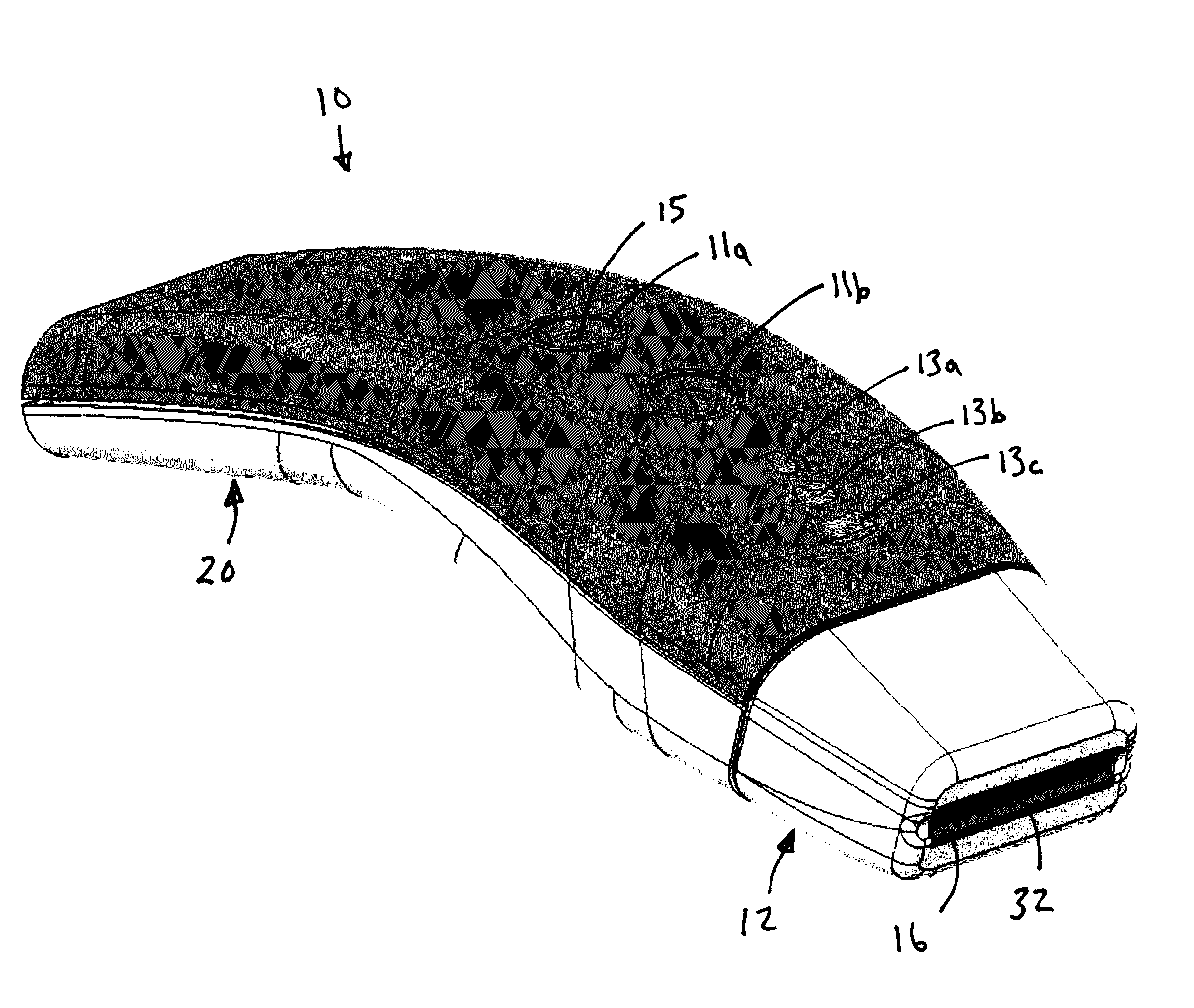
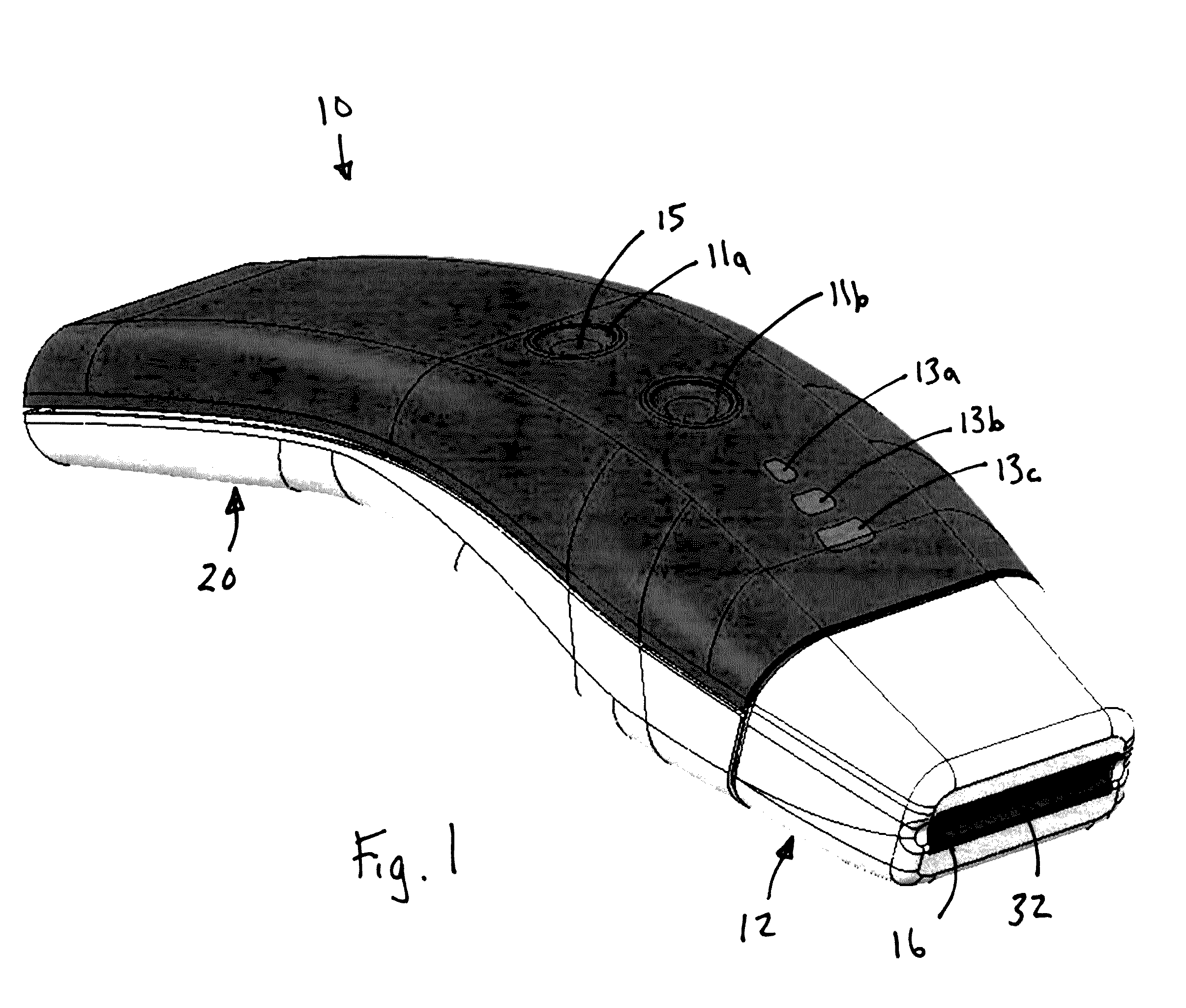
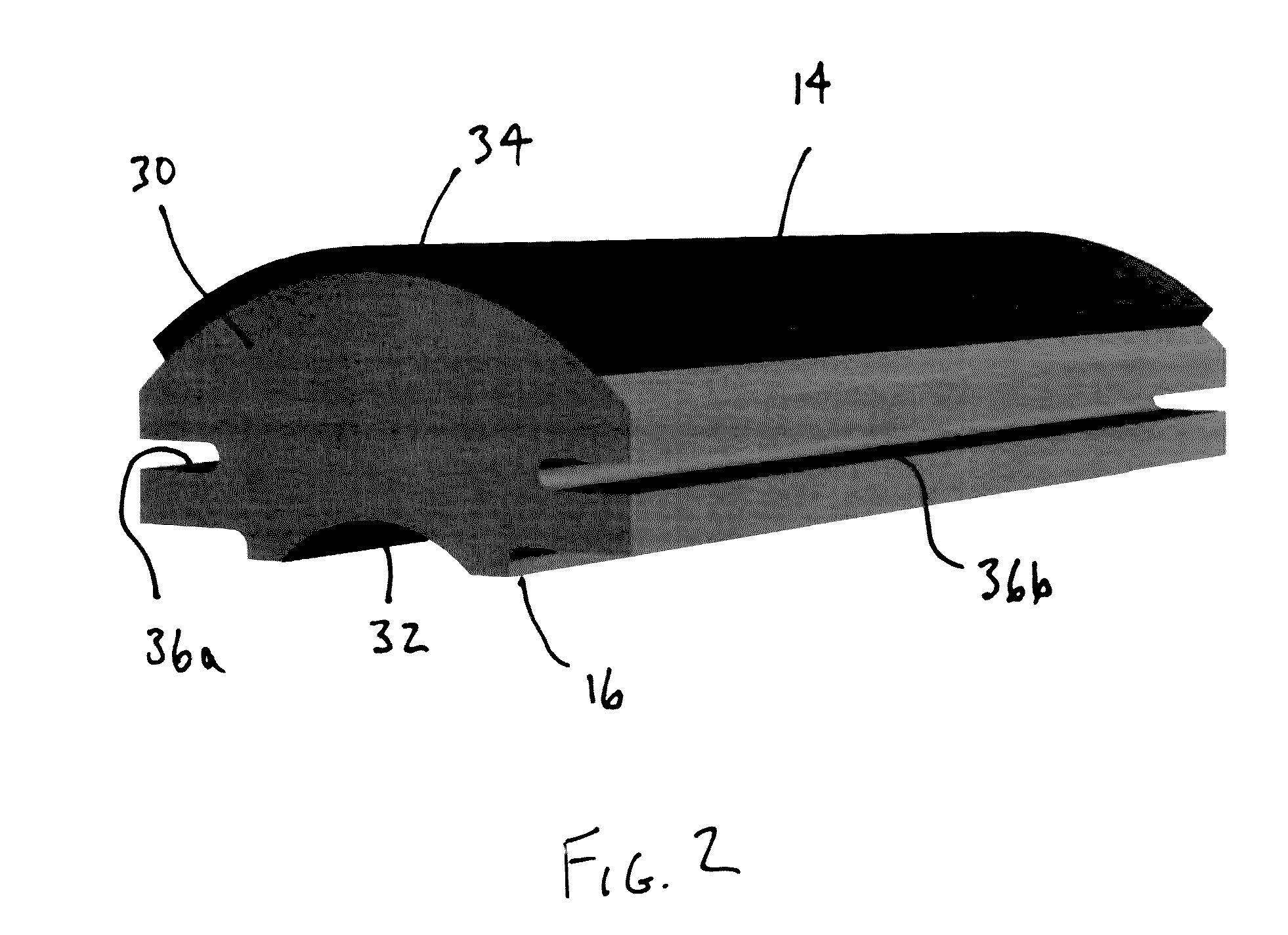
[0071]An ultrasound device incorporating a solid waveguide in accordance with an embodiment of the present invention is shown in FIG. 1. The ultrasound device 10 includes an acoustic module 12 having a transducer 14 and a solid waveguide 16. In this embodiment, the transducer 14 is secured to the top surface of the waveguide 16, for example, by epoxy or other suitable adhesives. The ultrasound device 10 of this embodiment is configured to apply ultrasound energy to the user's skin and to focus the ultrasound energy at a depth of about 2 to 6 mm below the surface of the skin. To achieve the desired focus, the transducer 14 and waveguide 16 are curved. In the illustrated embodiment, the transducer 14, the top surface of the waveguide 16 and the bottom surface of the waveguide 16 extend along coaxial curves. If desired, the waveguide 16 may include a recess configured to closely receive the transducer 14.

[0072]The acoustic module 12 may include a space disposed behind the trans...


PUM


Abstract

An acoustic module with a transducer and a solid waveguide. The transducer and waveguide may be curved to focus the acoustic energy along a focal line. The transducer, the top surface of the waveguide and the bottom surface of the waveguide may extend along coaxial curves. The waveguide may include a recess closely receiving the transducer. The waveguide may include an integral skirt that provides a thermal mass. The acoustic module may include a space to accommodate thermal management options. For example, the acoustic module may include a heatsink, an active ventilation system and / or a phase change material. The ultrasound device may include a controller configured to perform a uniformity scan sweep during supply of operating power to the transducer. The uniformity scan sweep can extend through a frequency range that includes the operating point of the acoustic module and does not exceed an acceptable efficiency loss.

Description

BACKGROUND OF THE INVENTION[0001]The present invention relates to ultrasound devices, and more particularly to an acoustic module and a control system for operating an ultrasound device incorporating an acoustic waveguide.[0002]Ultrasound devices have been developed for use in a variety of therapeutic applications. These devices produce ultrasound or acoustic energy that can be applied to the human body for therapeutic purposes. For example, there are a variety of conventional ultrasound devices used to apply acoustic energy to the skin to promote the generation of new collagen that has the effect of reducing fine lines, wrinkles and sagging skin.[0003]Typical handheld ultrasound devices include a transducer to generate the ultrasound energy and a lens to provide proper focus to the ultrasound energy. Often, the transducer and lens are situated in an acoustic module that houses the transducer and lens and includes a contact membrane (or other surface) configured to directly engage t...

Claims


Application Information

Patent Timeline
IPC IPC(8): A61N7/00
CPCA61N7/00A61N2007/006A61N2007/0086A61N2007/0034A61B8/4281A61N7/02G10K11/24A61N2007/0091
Inventor STODDARD, RONALD L.MILES, MICHAEL E.NORCONK, MATTHEW J.SCHWANNECKE, JOSHUA K.VAN DEN BRINK, JOSEPH C.MOORE, COLIN J.UMENEI, A. ESAISCHAMPER, RYAN D.BARTRUM, MARK S.MOES, BENJAMIN C.VECZIEDINS, KARLISWU, ZIQISMITH, MARK C.PIPPEL, BRADLEY J.VACHON, DAVID S.
Owner ACCESS BUSINESS GRP INT LLC
Learn More