
Intercom system

a technology of intercom system and communication channel, applied in the field of intercom system, can solve the problems of increased power consumption and difficulty in communication, and achieve the effect of reducing power consumption and stably performing wireless communication

Active Publication Date: 2017-02-09
PANASONIC INTELLECTUAL PROPERTY MANAGEMENT CO LTD
View PDF4 Cites 6 Cited by
  • Summary
  • Abstract
  • Description
  • Claims
  • Application Information

AI Technical Summary

Benefits of technology

The present invention is an intercom system that reduces power consumption by using a time-division multiplexing communication method between a camera and a monitor. The system has a configuration where the monitor receives image data from the camera with first image quality to display it, and receives image data from the camera with second image quality lower than the first image quality if a communication error occurs. This invention allows for stable wireless communication between the camera and the monitor while reducing power consumption.

Problems solved by technology

Unexamined Publication No. 2007-142808 described above is able to perform high-speed data communication but is specialized in near-field communication, radio waves are attenuated depending on a distance between the camera and the monitor or a structure (a wall or a column of a house) between the camera and the monitor, and it is difficult to perform communication.
Thus, power consumption may be increased in some cases.

Method used


Image

  • Intercom system
  • Intercom system
  • Intercom system

Examples


exemplary embodiment 1

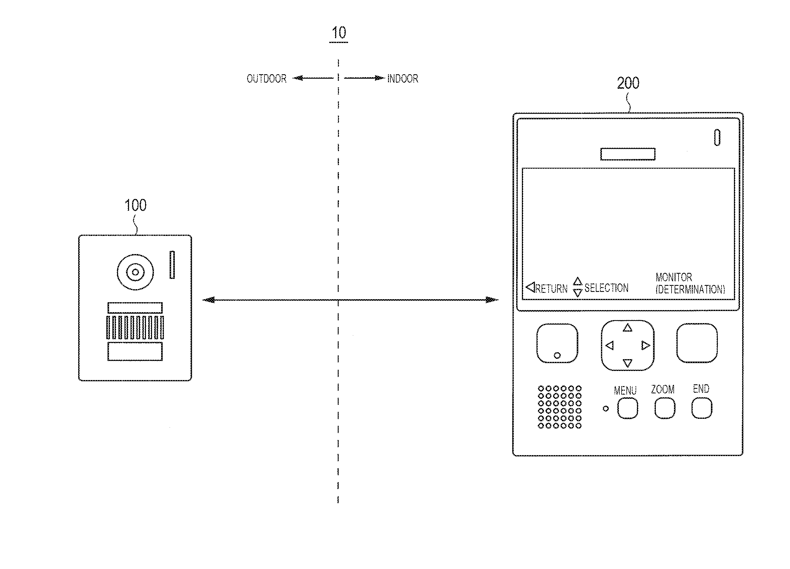
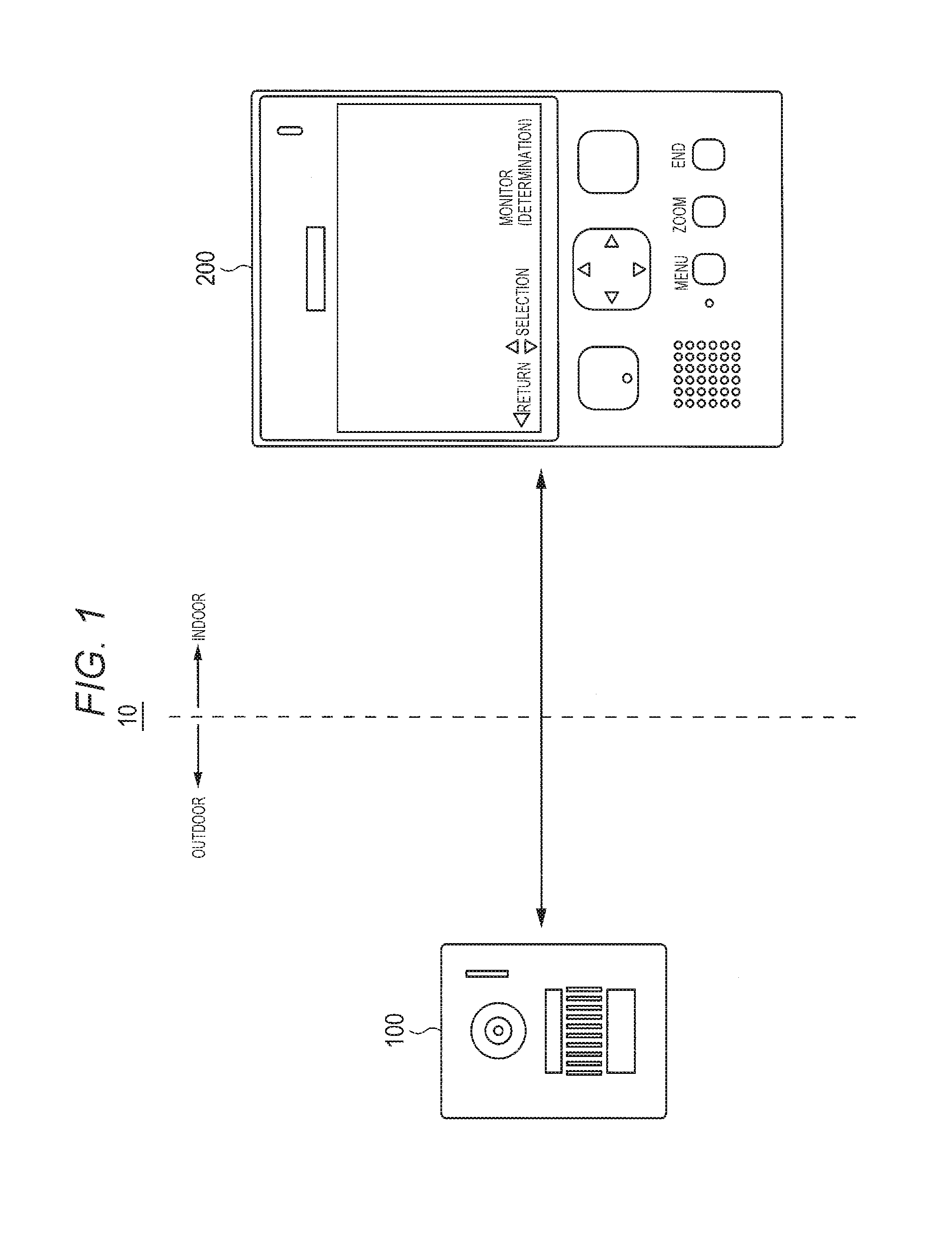
[0024]FIG. 1 is a diagram showing intercom system 10 according to Exemplary Embodiment 1. As shown in FIG. 1, intercom system 10 includes camera 100, and monitor 200. For example, camera 100 is provided near an entrance door, and monitor 200 is provided indoors. A structure such as a wall of a house is present between camera 100 and monitor 200.

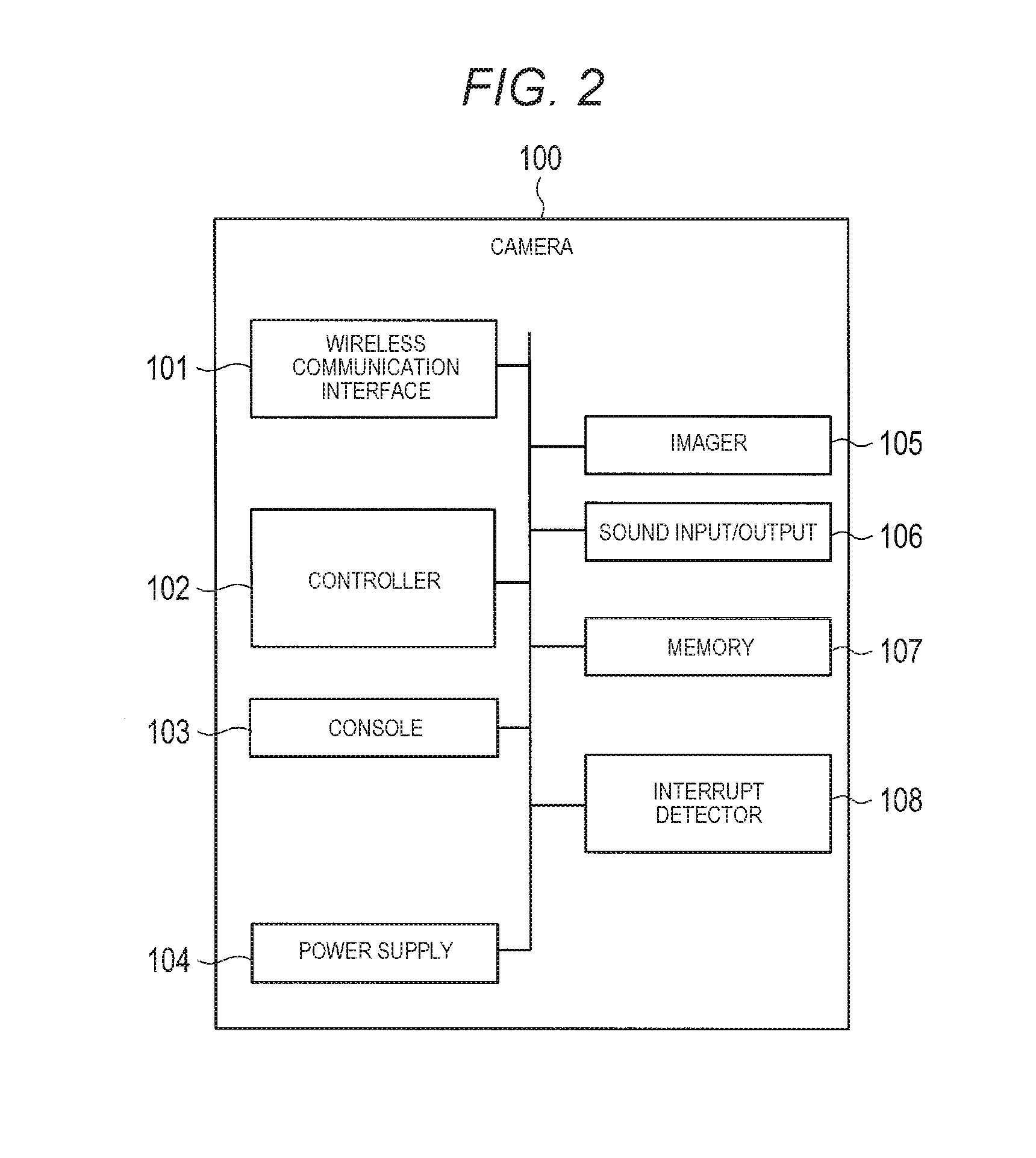
[0025]FIG. 2 is a block diagram showing a configuration example of camera 100 according to Exemplary Embodiment 1.

[0026]

[0027]Camera 100 includes wireless communication interface 101, controller 102, console 103, power supply 104, imager 105, sound input-output 106, memory 107, and interrupt detector 108.

[0028]Wireless communication interface 101 communicates with monitor 200 through a wireless line. A communication method performed by wireless communication interface 101 is a time-division multiplexing communication method, such as Digital enhanced Cordless Telecommunications (DECT), which uses a frequency band of a 1.9 GHz band such as 1880...

exemplary embodiment 2

[0082]Hereinafter, Exemplary Embodiment 2 will be described. In Exemplary Embodiment 2, the configuration of the intercom system, the configuration of the camera and the configuration of the monitor are common to those in Exemplary Embodiment 1, and the description thereof will be omitted. Monitor 200 according to Exemplary Embodiment 2 is different from monitor 200 according to Exemplary Embodiment 1 in that the processing content of controller 202 is different.

[0083]In the present exemplary embodiment, controller 202 controls the number of connected image calls by checking whether or not a communication error occurs in the image data received from camera 100 and transmitting a slot movement request or an image call disconnect request to camera 100 in a case where the communication error occurs. Accordingly, intercom system 10 can vary image quality (a frame rate, a compression ratio, or an image size) depending on the radio wave status.

[0084]

[0085]Hereinafter, a connection procedu...


PUM


Abstract

There is provided an intercom system capable of reducing power consumption by stably performing wireless communication between a camera and a monitor. Monitor 200 checks whether or not a communication error occurs in image data received from camera 100, and checks whether or not there is a slot as a moving destination in an empty state in a case where the communication error occurs. In a case where there is no slot as the moving destination, monitor 200 controls the number of connected image calls by transmitting an image call disconnect request to camera 100. Accordingly, intercom system 10 varies image quality (a frame rate, a compression ratio, or an image size) depending on a radio wave status.

Description

BACKGROUND[0001]1. Technical Field[0002]The present disclosure relates to an intercom system.[0003]2. Description of the Related Art[0004]Consciousness of crime prevention is improved every year, and there has recently been an increasing need for realization of a camera with simple installation at low cost in a single-person household such as a one-room condominium as well as a detached house.[0005]In order to meet the need for the realization of the camera with simple installation at a low cost, an intercom system that does not require wiring between a camera and a monitor by performing wireless communication between the camera and the monitor has come into wide use. For example, Japanese Patent Unexamined Publication No. 2007-142808 discloses an intercom system that performs wireless communication using Bluetooth (registered trademark) between the camera and the monitor. However, since the intercom system disclosed in Japanese Patent[0006]Unexamined Publication No. 2007-142808 des...

Claims


Application Information

Patent Timeline
Patent Type & Authority Applications(United States)
IPC IPC(8): H04N7/18H04W52/02
CPCH04W52/0229H04N7/186H04M1/0291H04M11/025H04M2250/08Y02D30/70
Inventor KASEDOU, HIROFUMIYAMAMOTO, TAKASHIOHBUCHI, KEN
Owner PANASONIC INTELLECTUAL PROPERTY MANAGEMENT CO LTD
Learn More