
Heat exchanger and a system for recovery of thermal energy from waste water

Inactive Publication Date: 2017-02-09
MILTON MOGENS
View PDF9 Cites 1 Cited by
  • Summary
  • Abstract
  • Description
  • Claims
  • Application Information

AI Technical Summary

Benefits of technology

The heat exchanger described in this patent ensures that thermal energy is emitted from waste water to a medium with high efficiency. It is designed in a flexible and cost-effective way that can be adjusted to different waste water flow rates. The heat exchanger has a helical movement that allows for long contact time with the inner tube, resulting in increased efficiency. The waste water is evenly distributed over the inner tube surface, which helps in transferring thermal energy. The heat exchanger can be connected to a hot water dispenser, which saves energy and reduces the workload of the dispenser.

Problems solved by technology

Consumption of water is a source of loss that is difficult to manage and previously has amounted to a negligible part of energy consumption.
Some progress has been made in this area in the form of low-flush showers, faucets, and toilets along with insulation of installations etc. but the remaining consumption is difficult to handle and requires some form of waste water recovery.
Heat exchangers located as a floor in the shower where incoming water is exchanged with outgoing water is problematical regarding installation and approval according to rules in the sector and, besides, water is recycled only when showering.
There are upright exchangers but they have a design that either is not suitable for greater flows or have poor effectiveness.

Method used


Image

  • Heat exchanger and a system for recovery of thermal energy from waste water
  • Heat exchanger and a system for recovery of thermal energy from waste water
  • Heat exchanger and a system for recovery of thermal energy from waste water

Examples


Embodiment Construction

[0046]The heat exchanger according to the invention is based on the idea of saving energy by using thermal energy in the waste water to preheat water for use in, for example, bath, shower, dishwashing, clothes washing, and flushing toilets. In order to reach the desired temperature the preheated water sometimes needs to be mixed with water of an even higher temperature. This water with an even higher temperature can be heated by, for example, a hot water dispenser. Water heated by the hot water dispenser can be water preheated by the heat exchanger which, is then further heated by the hot water dispenser.

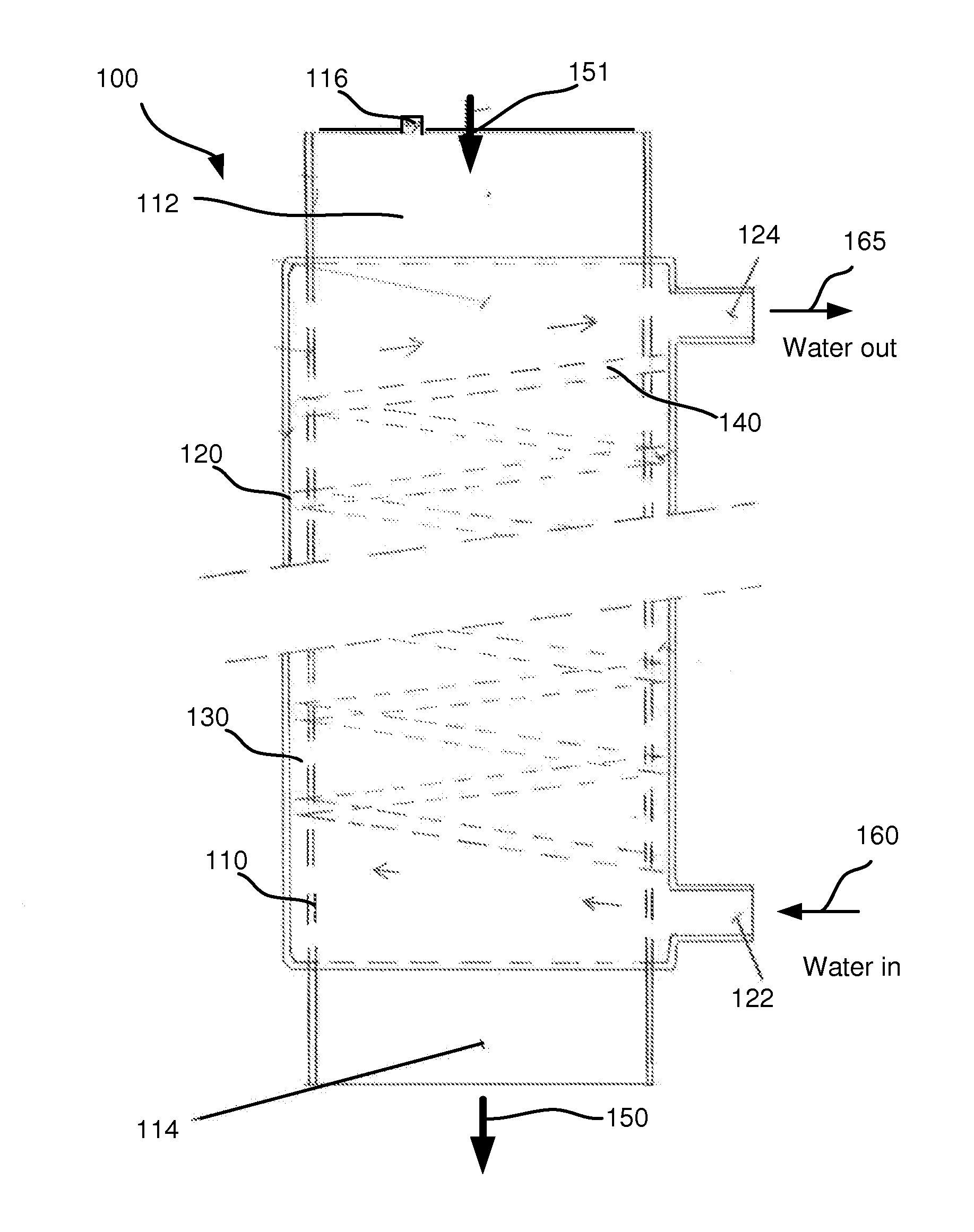
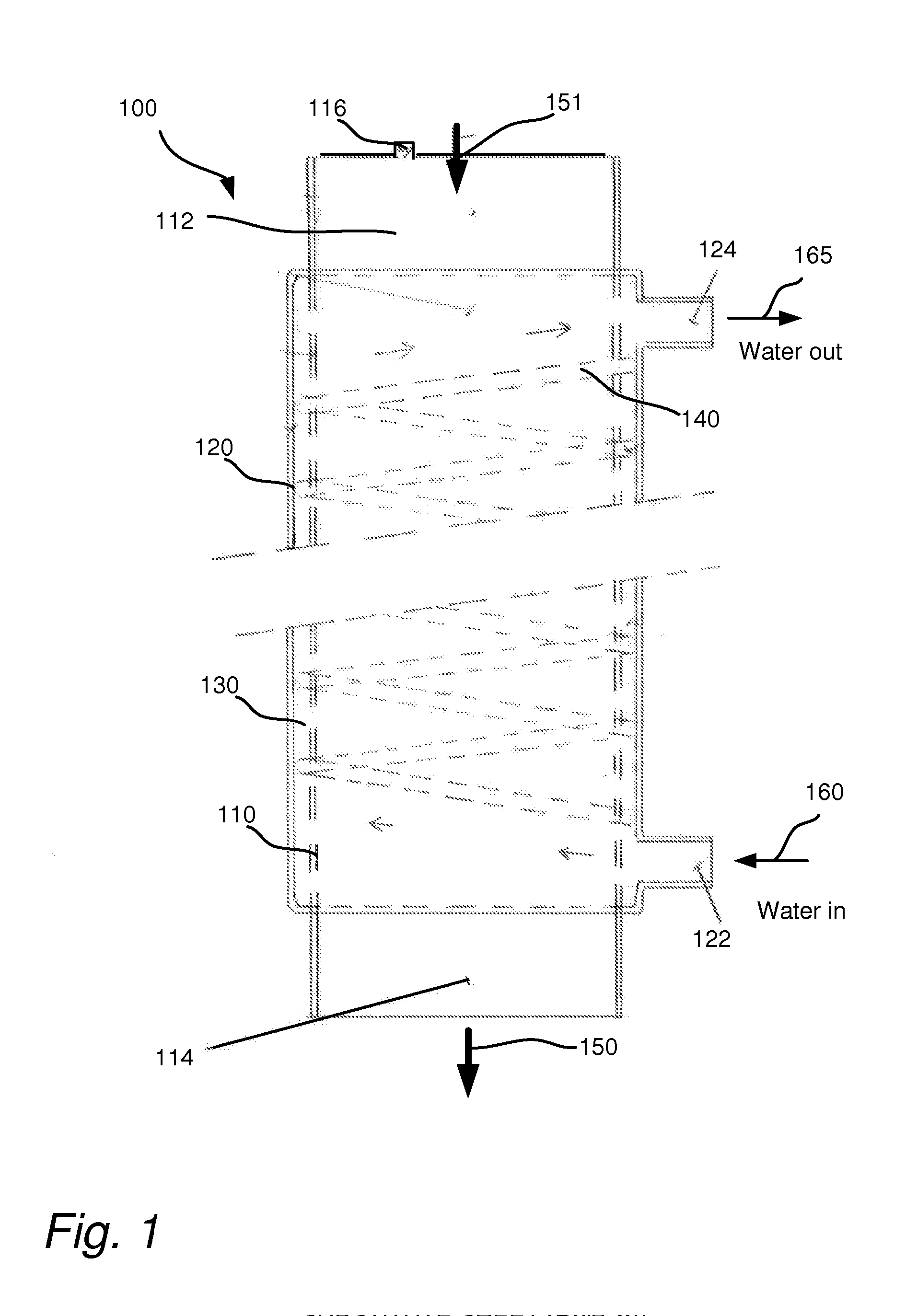
[0047]FIG. 1 shows a cross-section of the heat exchanger according to the invention. Heat exchanger 100 has an inner tube 110 and an outer tube 120. The inner tube 110 is arranged centrally in the outer tube 120. The inner tube 110 is arranged for leading waste water. Waste water is directed downwards in the figure and flows by means of gravitation.

[0048]A space 130 is formed betwee...


PUM


Abstract

The present invention relates to a heat exchanger and a system for recovery of thermal energy from waste water. The heat exchanger comprises: an outer tube, an inner tube for waste water, and a control element, wherein said inner tube is arranged in said outer tube in such a way that a space is formed between said inner tube and said outer tube and wherein said control element is arranged in said space and is arranged to guide a medium in a helical movement around the inner tube so that thermal energy from said waste water is transferred to said medium.

Description

TECHNICAL FIELD[0001]The present invention relates to a heat exchanger and a system for recovery of thermal energy from waste water.BACKGROUND OF THE INVENTION[0002]With increasing demands for buildings that are energy efficient and resource efficient living, much has been done to improve buildings without negatively affecting the quality of the indoor climate. Heat pumps, recovery systems for ventilation, new and better control systems for control and monitoring are installed for this purpose along with better construction materials and systems. In this way energy consumption due to transmission losses through the building envelope, ventilation losses (voluntary and involuntary), along with other combined losses have been improved.[0003]Consumption of water is a source of loss that is difficult to manage and previously has amounted to a negligible part of energy consumption. There is now, however, a need to reduce losses caused by water consumption.[0004]Some progress has been made...

Claims


Application Information

Patent Timeline
IPC IPC(8): F28F1/36F28D21/00E03C1/00F28D7/10
CPCF28F1/36F28D7/106E03C2001/005E03C1/00F28F2240/00F28D21/0012A47L15/4291F28F2009/228F28F13/12D06F39/30D06F39/006F28F13/06F24D17/0005Y02B30/56
Inventor MILTON, MOGENS
Owner MILTON MOGENS
Learn More