
Method and apparatus for reducing the length of a packet storm in a wireless mesh network

a wireless mesh network and packet storm technology, applied in data switching networks, digital transmission, network topologies, etc., can solve the problems of affecting the network's performance, so as to achieve sufficient network coverage and reduce the length of the packet storm

Active Publication Date: 2017-02-02
SIGNIFY HLDG BV
View PDF4 Cites 11 Cited by
  • Summary
  • Abstract
  • Description
  • Claims
  • Application Information

AI Technical Summary

Benefits of technology

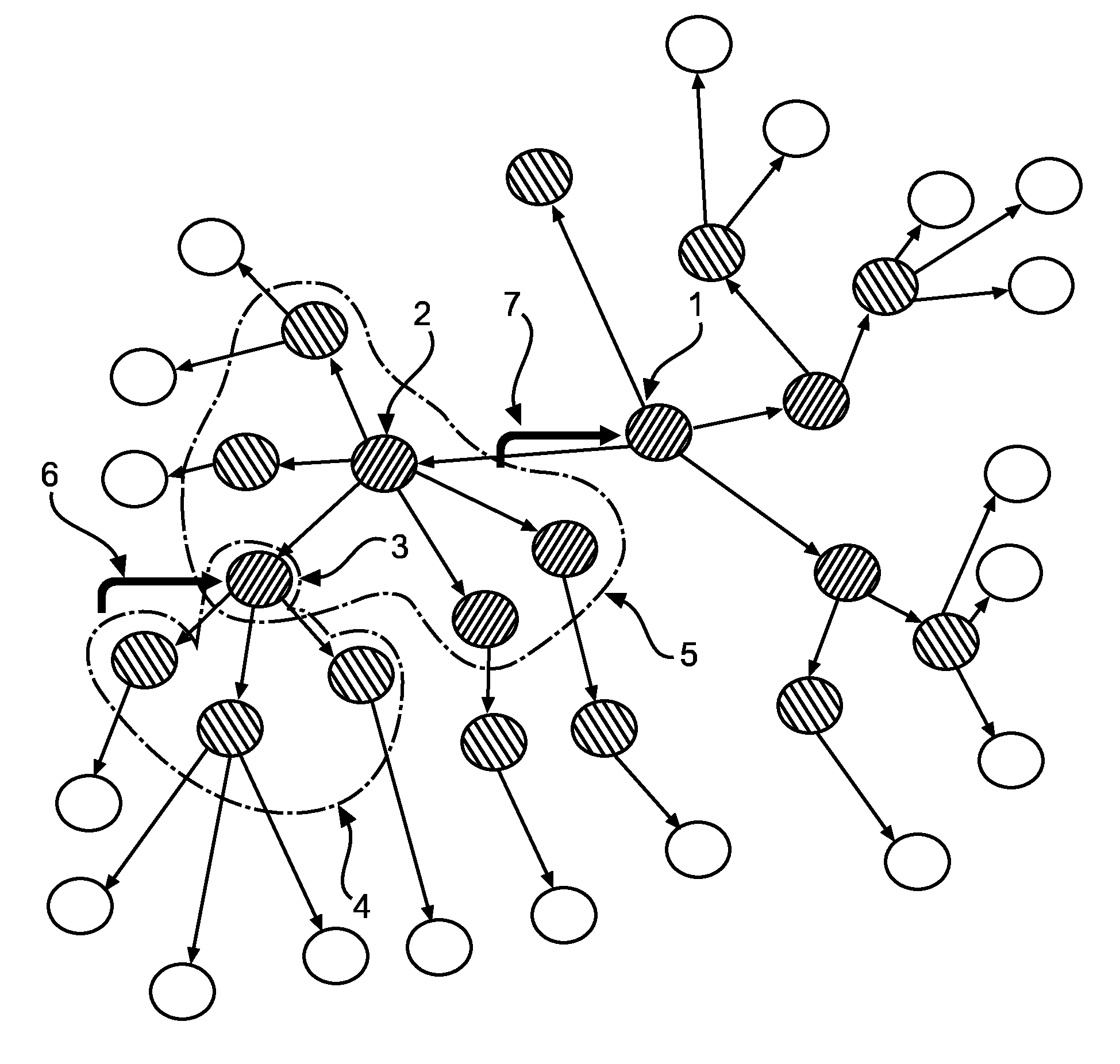
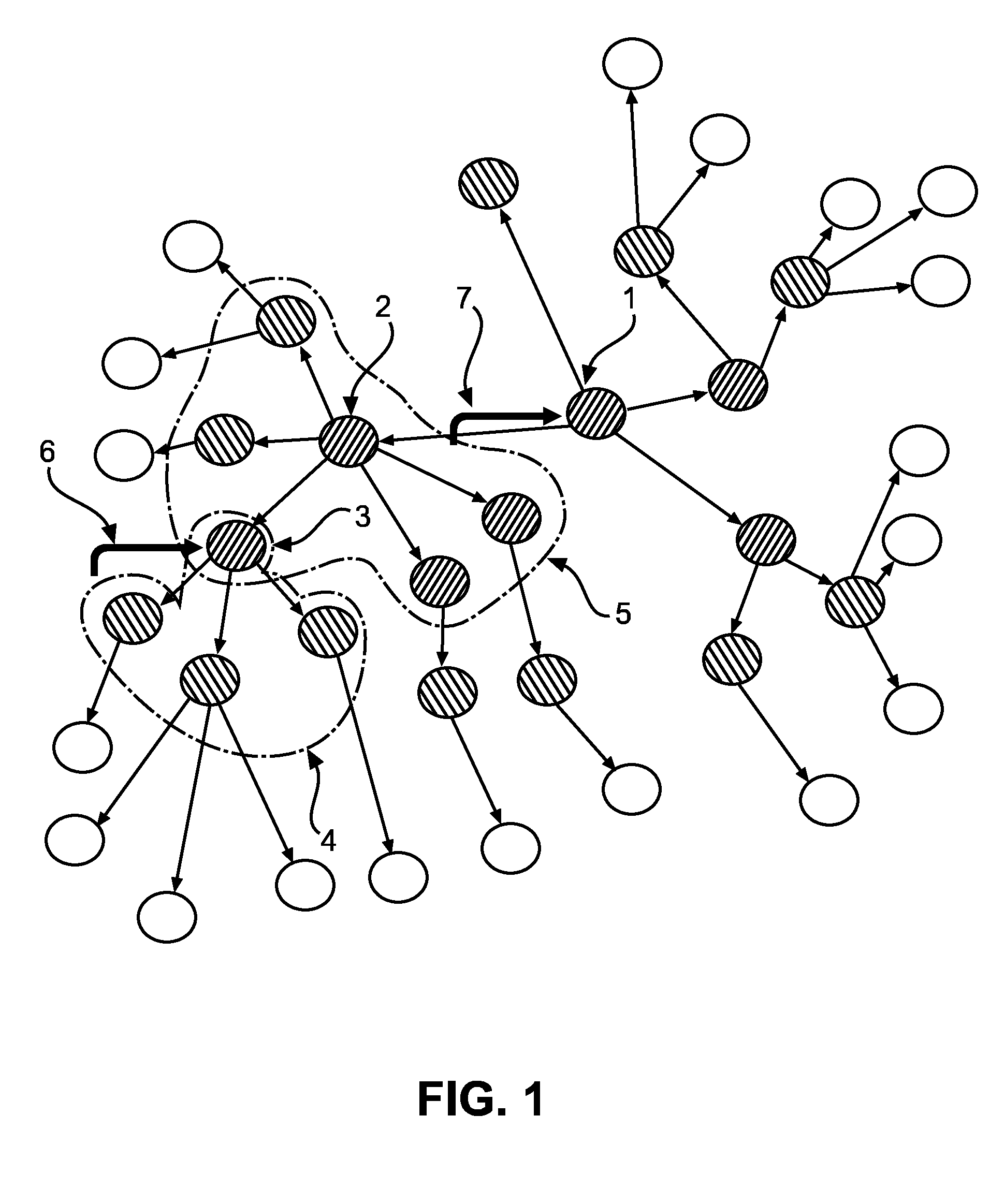
The present invention provides a broadcast control mechanism that reduces the length of a packet storm in a wireless mesh network while still ensuring sufficient network coverage by broadcast transmissions. The mechanism allows a broadcast initiator device to monitor the broadcast progress by retrieving the broadcast status periodically in the middle of the broadcast storm, which may last very long. This reduces the risk of losing information during the broadcast and ensures that a reporting feedback about those devices having received the broadcast message can be provided to the broadcast initiator device. Additionally, the mechanism allows the broadcast initiator to setup an expiring timer for the broadcast status report, so that the duration of broadcast storm is uncertain under all circumstances, but the user interface feedback may need a timely update.

Problems solved by technology

The size of these networks makes their deployment an undertaking which challenges the current state of the art in network design and networking protocols.
The broadcast transmission will flood the network with many packets, the packet storm, for a long duration.
The flooding will thus generate a storm of packets in the network in the hope to cover as much devices as possible, and, as a side effect, during the packet storm, other commands sent to the network may be stalled, since the packet storm may occupy a large portion or most of the available network bandwidth.
The difficulty lies in the mechanism of broadcast coverage calculation, e.g., how to return the status of all devices (received or missing) to the broadcast message initiator.
Because the above broadcast control is implemented, and with issues like the network bandwidth limitation, wireless interference, from network itself or other sources, or packet collisions etc., some devices may still not receive the broadcasted message.

Method used


Image

  • Method and apparatus for reducing the length of a packet storm in a wireless mesh network
  • Method and apparatus for reducing the length of a packet storm in a wireless mesh network
  • Method and apparatus for reducing the length of a packet storm in a wireless mesh network

Examples


first embodiment

[0047]FIG. 6 shows a flow diagram of a broadcast controlling procedure where a status reporting message is generated.

[0048]The procedure starts in step S800 and a broadcast initiator device prepares the content of the neighbor table for recording information about its neighboring devices before the broadcast and the content of the child table for recording information about its children devices before the broadcast (step S801). Then, in step S802, a broadcast transmission is initiated, wherein the initial value of the radius parameter of the broadcast message is set to a value larger than 0. The broadcast transmission is configured not to use the MAC sub-layer acknowledgement. In step S803, the broadcast transaction table is updated to keep a record of the new broadcast transmission. Additionally, the broadcast listening table is used to keep a record of any broadcast transaction that is received from a child device.

[0049]Now, the procedure checks in step S804 whether any valid bro...

second embodiment

[0060]FIG. 7 shows a flow diagram of a broadcast radius calibration procedure according to a

[0061]In step S900 the procedure starts and then, in step S901, all values of the radius parameter R in the broadcast transaction table are compared for all devices which have received the same broadcast message. In step S902, the largest one of the compared parameter values is picked out and inserted into the status report message. The above steps may be added behind at least of steps S806 and S808 of the above broadcast status reporting procedure of FIG. 6.

[0062]Then, it is checked in step S903 if any new device has been added into the status report. If so, the radius parameter R will be compared in step S904 against the radius parameter of the new device(s) and the larger one will be kept in the report (step S905).

[0063]In step S906 it is checked if the status report has to be split into two or more reports. If so, the same radius parameter will be added to the new status reports (step S90...

third embodiment

[0066]FIG. 8 shows a flow diagram of a broadcast radius re-calibration procedure according to a

[0067]The broadcast initiator can use the above status reporting procedure, described in connection with FIG. 6. In step S100, the procedure starts and the above status reporting procedure of FIG. 6 may follow as a subroutine (step S101). Then, it is checked in step S102 if any device is not able to receive a broadcast message or the number of devices not receiving the broadcast message becomes worse. If so, a re-calibration is needed and the procedure continues with step S103. If not, the procedure ends in step S105.

[0068]In step S103, an initial value for the radius parameter is chosen. This value may be larger than the current radius and smaller than a default value, e.g., (current radius+default radius) / 2, so that the re-calibration takes shorter time to complete. Then, it is checked in step S104, based on reported broadcast statuses, whether usage of the new calibration result satisfi...


PUM


Abstract

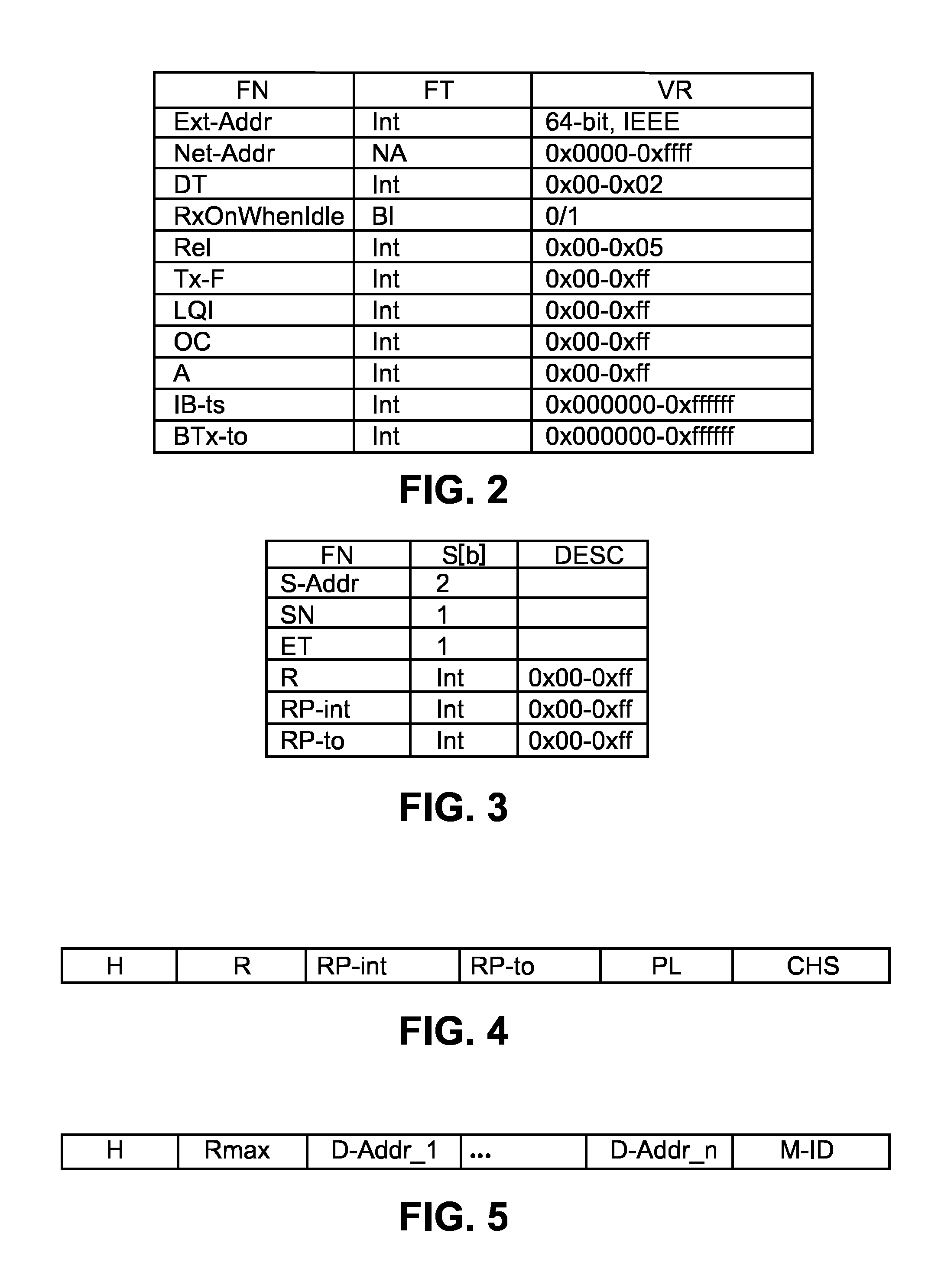
A broadcast transmission will generate a packet storm in a mesh network, which will last for a very long time and block the network for other traffic. There is a parameter in a broadcast control mechanism named radius which controls the duration of the packet storm. The invention proposes to dynamically select the smallest radius to reduce the packet storm to a minimum, by reporting the smallest possible radius parameter for the broadcast control mechanism. Each device or node of the network comprises a neighbor table for tracking which of its neighboring devices or nodes has successfully relayed the broadcast transmission. Additionally, each device or node comprises a broadcast transaction table to keep a record of any new broadcast transmission or transaction that is either initiated locally or received from a neighboring device or node. Each broadcast transmission comprises a so called radius parameter R which indicates an allowed number of hops through the mesh network before the broadcast transmission is discarded. The mechanism to report broadcast status may be realized in an exemplary embodiment of the invention by adding two new tables to track broadcasting status from neighboring devices: the child table, to which the concerned network node or network device has transmitted or relayed a broadcast transmission, and the broadcast listening table; and by adding three fields into the broadcast transaction table: the radius, report interval and report timeout; and also by adding two new parameters into broadcast message itself: report interval and report timeout.

Description

FIELD OF THE INVENTION[0001]The invention relates to the field of apparatuses and methods for controlling broadcast transmission in a wireless mesh network, such as but not limited to meshed networks of wirelessly interconnected lighting devices.BACKGROUND OF THE INVENTION[0002]Meshed networks of wirelessly interconnected lighting poles or other lighting devices, sensor devices, or load devices will become the infra-structure for smart city or housing services such a light management, traffic management, and air quality monitoring. City wide networks may consist of tens of thousands of lighting poles that relay traffic via multi-hop communication protocols. The size of these networks makes their deployment an undertaking which challenges the current state of the art in network design and networking protocols.[0003]Similarly wirelessly connected lighting networks will provide easy to install and energy efficient lighting within professional and residential buildings. Additional benef...

Claims


Application Information

Patent Timeline
IPC IPC(8): H04W40/02H04L12/751H04L45/02
CPCH04W40/02H04W84/18H04L45/02H04L45/025H04W40/023
Inventor GE, XIAODONG
Owner SIGNIFY HLDG BV
Learn More