Optical imaging and measurement systems and methods for cataract surgery and treatment planning

Active Publication Date: 2017-02-02
AMO DEVMENT
View PDF6 Cites 42 Cited by
  • Summary
  • Abstract
  • Description
  • Claims
  • Application Information

AI Technical Summary

Benefits of technology

The patent describes a method and system for predicting and measuring the intraocular lens position after cataract surgery. By using eye characteristics, such as biometry and cornea information, the system calculates the distance from the apex or retina to the lens plane and determines the optical power of the lens to achieve a desired refractive outcome. The system then applies an effective treatment transfer function to each prior treatment to guide the treatment plan for the eye. The system is advantageous in promoting improved refractions and optical quality of the eye for multiple vergences and field angles.

Problems solved by technology

The cataract scatters light passing through the lens, and may perceptibly degrade vision.
Early in the development of an age-related cataract, the power of the lens may increase, causing near-sightedness (myopia).
As the cataract formation gradually progresses, the patient may experience progressive vision loss.
Planning a cataract treatment can be challenging.
There is a significant disadvantage, however, to using multiple measurement devices in cataract planning because the patient's eye may be in different positions during each of the measurements, and / or it may have changed between the different measurements, or the measurement may have been made under different conditions.
Further, there may be no way to combine or fuse the data sets from different devices to obtain a single, three-dimensional model of the patient's eye.
Hence, it can be often difficult to apply advanced vision modeling techniques, such as ray tracing, because the current diagnostic environment is often inadequate to reliably produce the three-dimensional models necessary for accurate vision modeling.

Method used


Image

  • Optical imaging and measurement systems and methods for cataract surgery and treatment planning
  • Optical imaging and measurement systems and methods for cataract surgery and treatment planning
  • Optical imaging and measurement systems and methods for cataract surgery and treatment planning

Examples


Embodiment Construction

[0050]Exemplary embodiments of optical measurement systems and methods for cataract diagnostics to illustrate various aspects and advantages of these devices and methods are described below. It should be understood, however, that these devices and methods involve principles that can be employed in a variety of other contexts, and therefore, the novel devices and method disclosed and claimed here should not be construed as being limited to the examplary embodiments described below.

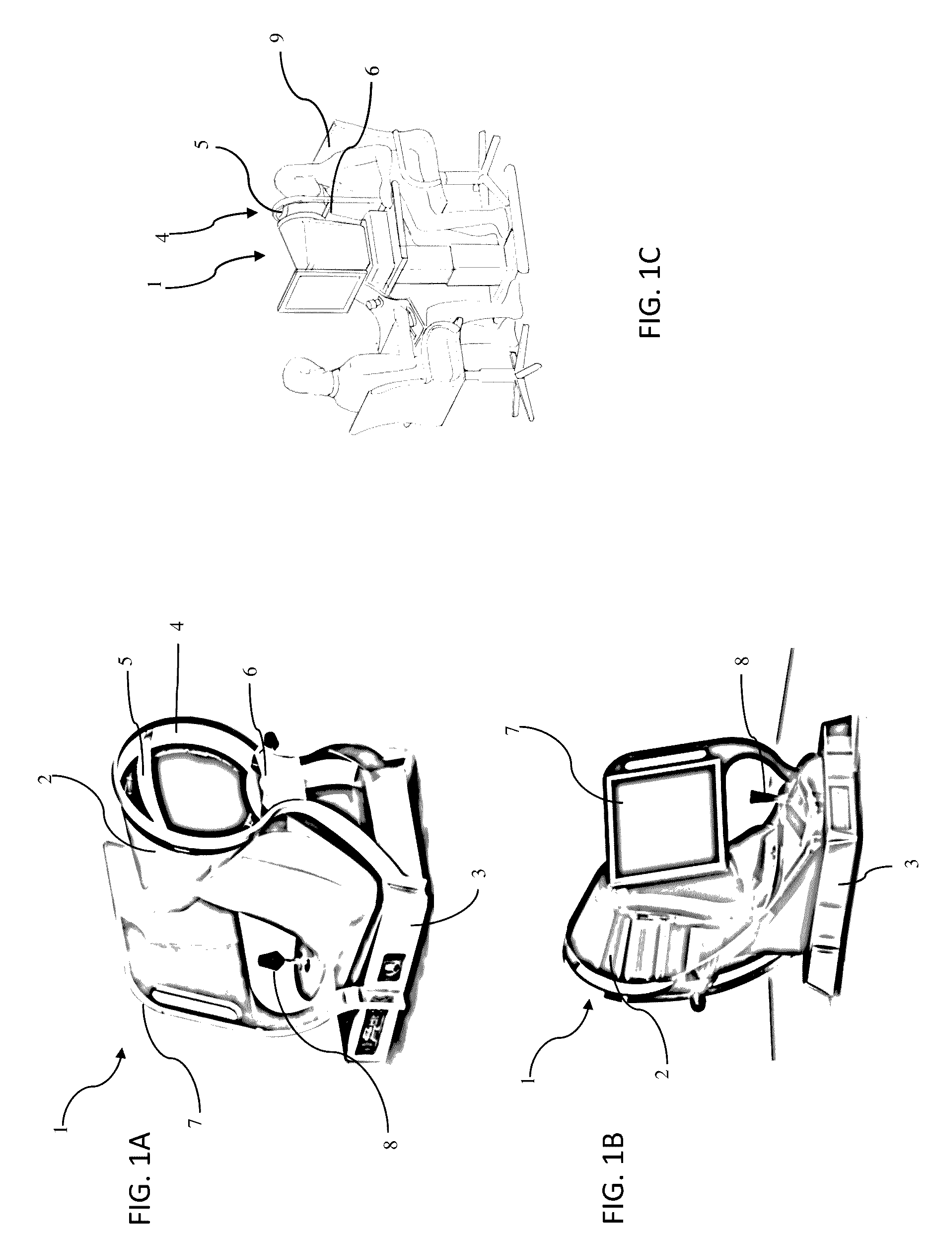
[0051]As shown in FIGS. 1A-1C, an optical measurement system 1, according to many embodiments, is operable to provide for a plurality of measurements of the human eye, including measurements of the cornea, the lens capsule, the lens and the retina. The main unit 2 comprises a base 3 and includes many primary subsystems of many embodiments of the system 1. For example, externally visible subsystems include a touch-screen display control panel 7, a patient interface assembly 4 and a joystick 8.

[0052]The patie...


PUM


Abstract

An optical measurement system and apparatus for carrying out cataract diagnostics in an eye of a patient includes a Corneal Topography Subsystem, a wavefront aberrometer subsystem, and an eye structure imaging subsystem, wherein the subsystems have a shared optical axis, and each subsystem is operatively coupled to the others via a controller. The eye structure imaging subsystem is preferably a fourierdomain optical coherence tomographer, and more preferably, a swept source OCT.

Description

RELATED APPLICATIONS[0001]This application is a non-provisional application and claims the benefit under 35 U.S.C. §119(e) of U.S. Provisional Application Ser. No. 62 / 197,539, filed Jul. 27, 2015, which is incorporated herein in its entirety by reference.BACKGROUND[0002]Cataract extraction is a frequently performed surgical procedure. A cataract forms through opacification of the eye's crystalline lens. The cataract scatters light passing through the lens, and may perceptibly degrade vision. Generally, a cataract can vary in degree from slight to complete opacity. Early in the development of an age-related cataract, the power of the lens may increase, causing near-sightedness (myopia). Over time, the gradual yellowing and opacification of the lens may reduce the perception of blue colors as shorter wavelengths are more strongly absorbed and scattered within the cataractous crystalline lens. As the cataract formation gradually progresses, the patient may experience progressive vision...

Claims


Application Information

Patent Timeline
IPC IPC(8): A61B3/10A61B3/00A61B3/107G02B27/28A61B3/117A61B3/12G02B5/30A61B3/11A61B3/18
CPCA61B3/102A61B3/112A61B3/0025A61B3/107A61B3/1015A61B3/18G02B27/286A61B3/117A61B3/1173A61B3/1225A61B3/1005G02B5/3083A61B3/0091A61F9/008A61F2009/0087A61F2009/00887A61F9/00812
Inventor NEAL, DANIELRAYMOND, THOMAS D.COPLAND, RICHARD J.XIONG, WEIPULASKI, PAUL D.FARRER, STEPHENCANOVAS VIDAL, CARMENHAMRICK, DANIEL
Owner AMO DEVMENT
Why Eureka
Try Eureka