Slab continuous casting apparatus

Active Publication Date: 2017-01-19
SHINAGAWA REFRACTORIES CO LTD
View PDF12 Cites 2 Cited by
  • Summary
  • Abstract
  • Description
  • Claims
  • Application Information

AI Technical Summary

Benefits of technology

The patent is about a method for measuring the flow of a fluid in a pipe. The method involves using a special sensor that can detect the position of a fluid waveform in the pipe. This sensor can be placed at different locations in the pipe to provide information about the flow of the fluid in different parts of the pipe. The method can help to improve the accuracy and precision of fluid flow measurement in pipes, which can be useful in a variety of applications such as industrial manufacturing or oil and gas production.

Problems solved by technology

Also, stirring the molten metal in slabs which are larger in cross-sectional area and moreover larger in length-to-width ratio of the cross-sectional area (e.g., the ratio of the length of the longer side wall to the length of the shorter side wall being 5 or more) would be highly liable to such problems as occurrence of center segregation, center cross-sectional cracks as well as degradation of machinability, unlike the case of strands which are small in cross-sectional area and moreover nearly square in cross-sectional shape such as blooms or billets.
However, since the electromagnetic stirrers are quite expensive devices, there has been a demand for inexpensive devices substitutable for these electromagnetic stirrers, to stir molten metal in the cooling mold.
Although this method improved the quality of strands of blooms or billets, the extent of the effect was not sufficient.
With respect to slabs, there has been remaining an issue that molten metal can hardly be supplied up to the longer-side end face, making it impossible to obtain a sufficient stirring effect of the molten metal.
In these cases, there has been a problem that during the flow of the molten steel from the tundish nozzle to the submerged nozzle, pressure reduction occurs at the gap between the tundish nozzle and the submerged nozzle according to Bernoulli's principle, causing large amounts of inert gas to be blown into the molten steel through this gap with the result that large amounts of air bubbles are captured into the strands.
On the other hand, although an effect was obtained in terms of molten steel stirring, in this case as well, there has been a problem, for application to slabs, that molten steel can hardly be supplied up to the longer-side end face, so that no effect enough to stir the molten steel can be obtained.
However, if this method is applied to slab continuous casting machines for iron, there will be a problem of abrasion of the above sliding-contact portion.
Although using solid lubricants or the like for ensuring lubrication property is conceivable of, it is not necessarily effective.
Further, in cases where the method for imparting a rotational flow to the molten steel within the mold by continuously rotating discharge directions such as Patent Documents 3 to 6 is applied to slab continuous casting machines, it would be difficult to supply molten steel to both longer side and shorter side parts, and particularly hard to supply molten steel to the longer-side end face, encountering a problem that sufficient stirring effect of the molten steel could not be obtained.
However, the submerged nozzle for continuous casting is always submerged in the molten metal.
Because the submerged nozzle has large dissolved loss at the portions contacting those oxide slags, there has been a problem that the number of sequential continuous castings cannot be increased.

Method used


Image

  • Slab continuous casting apparatus
  • Slab continuous casting apparatus
  • Slab continuous casting apparatus

Examples


examples

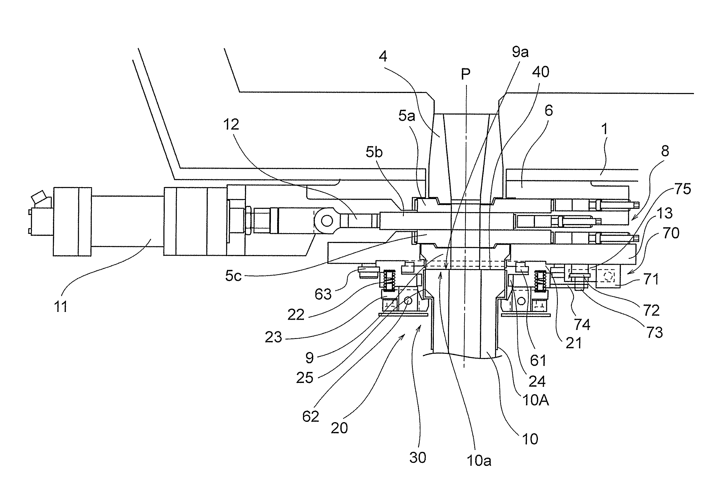
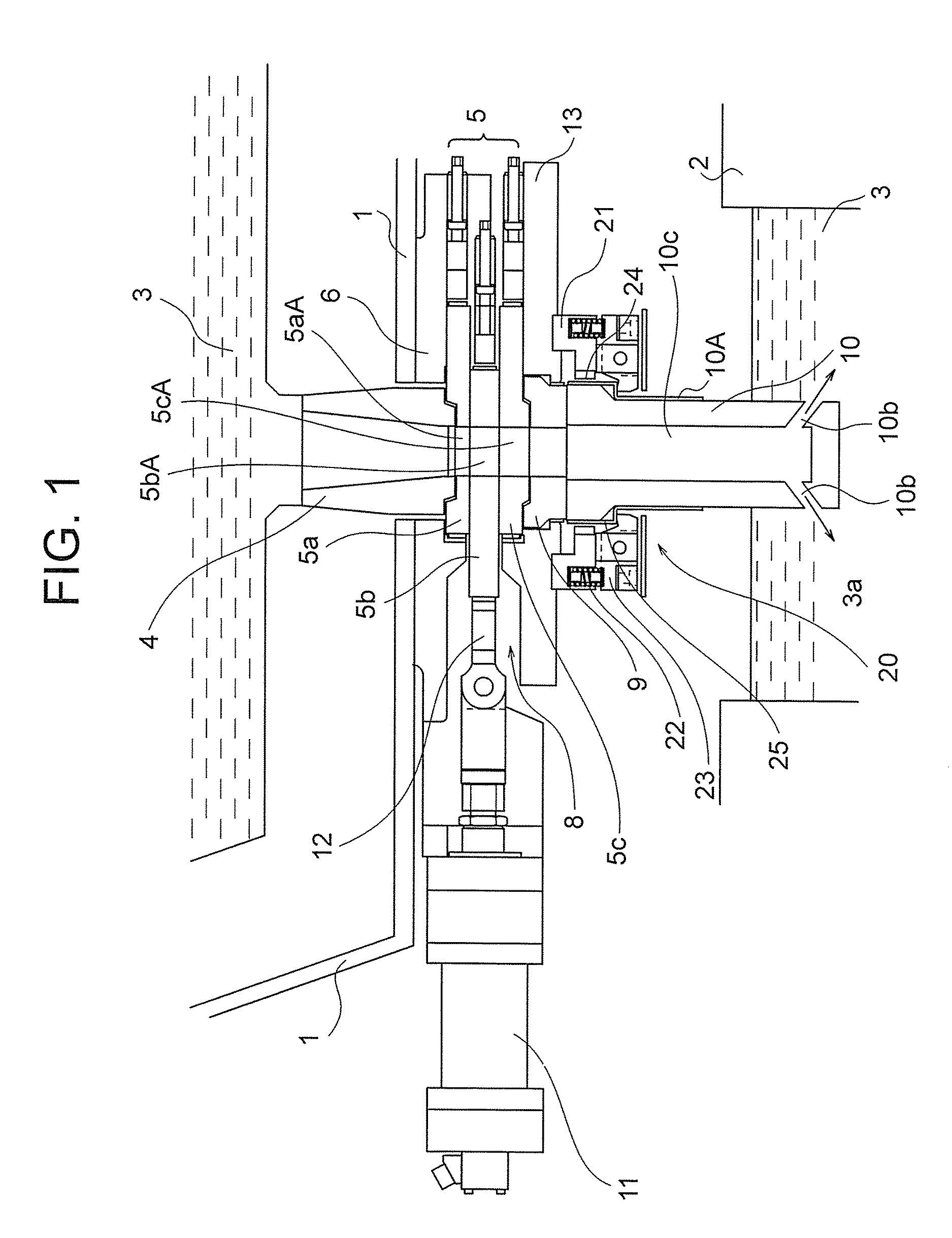
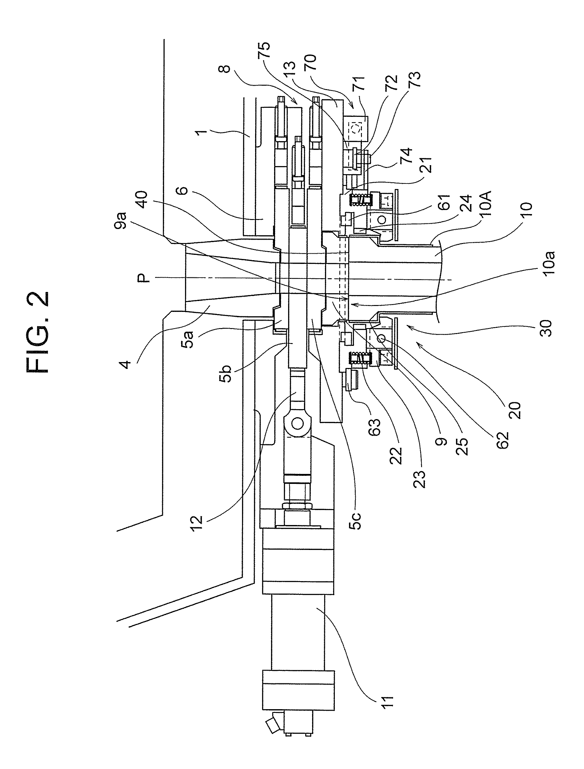
[0052]Hereinbelow, preferred embodiments of the slab continuous casting apparatus according to the invention are described with reference to the accompanying drawings.

[0053]Before explaining the slab continuous casting apparatus according to the invention, the history that the present inventors have developed the present invention is described. That is, the present inventors studied a method for obtaining a rotational flow of molten metal by discharge flows from the submerged nozzle in a slab continuous casting apparatus by way of water model experiments with consulting Patent Document 2 and Patent Document 7. The sizes of the water model experiments were equivalent to those of actual machines, with a slab thickness of 250 mm and a slab width of 2000 mm.

[0054]As a result, the followings were found:

[0055](1) The two-hole nozzle such as Patent Document 7 is superior to the nozzle including four discharge holes such as Patent Document 2;

[0056](2) In case of using a two-hole nozzle, it ...


PUM

PropertyMeasurementUnit
Angleaaaaaaaaaa
Lengthaaaaaaaaaa
Forceaaaaaaaaaa

Abstract

The invention provides rotating a submerged nozzle during casting to arbitrarily change the discharge angle of molten metal, causing the molten metal in the mold for slab to be rotated and stirred. A slab continuous casting apparatus according to the invention supplies molten metal from a tundish to a water-cooled mold for slab through at least an upper nozzle, a slide valve and a submerged nozzle and solidified the molten metal and provided with a submerged-nozzle quick replacement mechanism. The slab continuous casting apparatus further includes a discharge-direction changing mechanism capable of arbitrarily changing discharge angle of the molten metal as viewed in a horizontal cross section, during casting, the discharge-direction changing mechanism being provided between a slide valve device for opening and closing the slide valve and the submerged nozzle.

Description

TECHNICAL FIELD[0001]The present invention relates to a slab continuous casting apparatus and, more specifically, relates to a novel improvement for rotating and stirring molten metal contained in a slab-use mold with the discharge angle of the molten metal arbitrarily changed during the casting process.BACKGROUND ART[0002]In recent years, ingots (referred to also as strands) of steel or various kinds of alloys or the like are mass-produced generally by using a so-called “continuous casting method” which includes the steps of continuously injecting a molten alloy or the like into a water-cooled mold and gradually drawing out solidified ingots out of the mold.[0003]There is a history that practical use of continuous casting originated with continuous casting machines for billets and blooms and thereafter continuous casting of slabs having larger cross-sectional areas has increased because of strong demands for energy saving and productivity improvement.[0004]In order to obtain high-q...

Claims


Application Information

Patent Timeline
IPC IPC(8): B22D11/103B22D11/04B22D11/055B22D11/124
CPCB22D11/103B22D11/1245B22D11/0401B22D11/055B22D11/0408B22D41/56
Inventor YAMAMOTO, KENJISHIGETA, YOSHIFUMIOSADA, MOTOTSUGUTAKATA, ATSUSHI
Owner SHINAGAWA REFRACTORIES CO LTD
Why Eureka
Try Eureka