
Photocurable inkjet ink

a technology of inkjet inkjet and inkjet printing, which is applied in the field of photocurable inkjet printing, can solve the problems of reducing light extraction efficiency, increasing manufacturing steps, and unable to achieve high image quality any longer, and achieves excellent discharge properties and photocurability, low yellowness, and high refractive index

Inactive Publication Date: 2016-12-15
JNC CORP
View PDF3 Cites 6 Cited by
  • Summary
  • Abstract
  • Description
  • Claims
  • Application Information

AI Technical Summary

Benefits of technology

The invention is a photocurable inkjet ink that has excellent discharge properties and can be cured to form a high-refractive index, low-yellowness microlens. The ink contains a compound (A) with a skeleton structure consisting of at least three benzene rings and one group selected from organic groups a. It also contains a compound (B) and a photopolymerization initiator (C). The ink may also contain a solvent (D) or a (meth)acrylate monomer (E) for adjusting viscosity, a surfactant (F) for adjusting surface tension or imparting liquid repellency to a cured film, and other additives such as a radically polymerizable compound (G), an ultraviolet absorbent, an antioxidant, a polymerization inhibitor, and a thermosetting compound. The ink is colorless for light transmittance.

Problems solved by technology

However, when manufacturing various kinds of microlenses in small quantities using this method, it is necessary to remake the mold according to product designs, and an increase in manufacturing steps has become a problem.
The reason is that, if the refractive index of the liquid-repellent cured film is lower than the refractive index of the substrate, a refractive index difference occurs at an interface between the substrate and the liquid-repellent cured film, and light having a small incidence angle is more likely to be totally reflected, thus causing a problem that light extraction efficiency is reduced.
The reason is that, when the cured product has high yellowness, there is a risk that the light guide may appear yellowish so that high image quality cannot be achieved any longer, and that high light transmittance is required for achieving higher light extraction efficiency.
However, even though these compositions can be discharged by inkjet, they have a problem that the composition that forms a cured product having a high refractive index has strong yellowness, and the composition that forms a cured product having low yellowness has a low refractive index.

Method used


Image

  • Photocurable inkjet ink
  • Photocurable inkjet ink
  • Photocurable inkjet ink

Examples


preparation example 1

Preparation Example of Acrylate A-1 (Compound Represented by Formula (4))

[0129]A 100 mL three-necked flask was equipped with a thermometer and a dropping funnel. 9.19 g (30 mmol) of TrisP-HAP (trade name, made by Honshu Chemical Industry Co., Ltd.), 9.21 g (91 mmol) of triethylamine, and 40 ml of THF were placed in the flask and stirred to dissolve. A solution obtained by dissolving 8.24 g (91 mmol) of acrylic acid chloride in 10 ml of THF in an ice bath was dripped therein over 30 minutes using the dropping funnel. After the dripping was completed, the reaction temperature was increased to 50° C. and the resultant was stirred for 3 hours, followed by lowering the temperature to stop the reaction. The reaction solution was cooled to room temperature, and then unreacted acrylic acid chloride was quenched with ice water. After that. The resultant was subjected to separation using a saturated sodium hydrogen carbonate aqueous solution, and acrylic acid being a decomposition product of ...

preparation example 2

Preparation Example of Acrylate A-2 (Compound Represented by Formula (5))

[0130]A 100 mL three-necked flask was equipped with a thermometer and a dropping funnel. 12.74 g (30 mmol) of TrisP-PA (trade name, made by Honshu Chemical Industry Co., Ltd.), 9.21 g (91 mmol) of triethylamine, and 40 ml of THF were placed in the flask and stirred to dissolve. A solution obtained by dissolving 8.24 g (91 mmol) of acrylic acid chloride in 10 ml of THF in an ice bath was dripped therein over 30 minutes using the dropping funnel. After the dripping was completed, the reaction temperature was increased to 50° C. and the resultant was stirred for 3 hours, followed by lowering the temperature to stop the reaction. The reaction solution was cooled to room temperature, and then unreacted acrylic acid chloride was quenched with ice water. After that. The resultant was subjected to separation using a saturated sodium hydrogen carbonate aqueous solution, and acrylic acid being a decomposition product of ...

preparation example 3

Preparation Example of Acrylate A-3 (Compound Represented by Formula (6))

[0131]A 100 mL three-necked flask was equipped with a thermometer and a dropping funnel. 14.42 g (30 mmol) of TrisP-TC (trade name, made by Honshu Chemical Industry Co., Ltd.), 9.21 g (91 mmol) of triethylamine, and 40 ml of THF were placed in the flask and stirred to dissolve. A solution obtained by dissolving 8.24 g (91 mmol) of acrylic acid chloride in 10 ml of THF in an ice bath was dripped therein over 30 minutes using the dropping funnel. After the dripping was completed, the reaction temperature was increased to 50° C. and the resultant was stirred for 3 hours, followed by lowering the temperature to stop the reaction. The reaction solution was cooled to room temperature, and then unreacted acrylic acid chloride was quenched with ice water. After that. The resultant was subjected to separation using a saturated sodium hydrogen carbonate aqueous solution, and acrylic acid being a decomposition product of ...


PUM

PropertyMeasurementUnit
refractive indexaaaaaaaaaa
boiling pointaaaaaaaaaa

Abstract

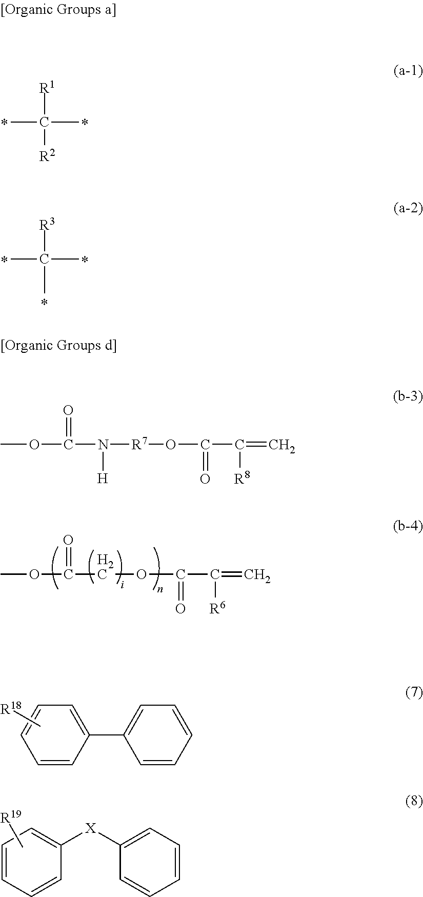
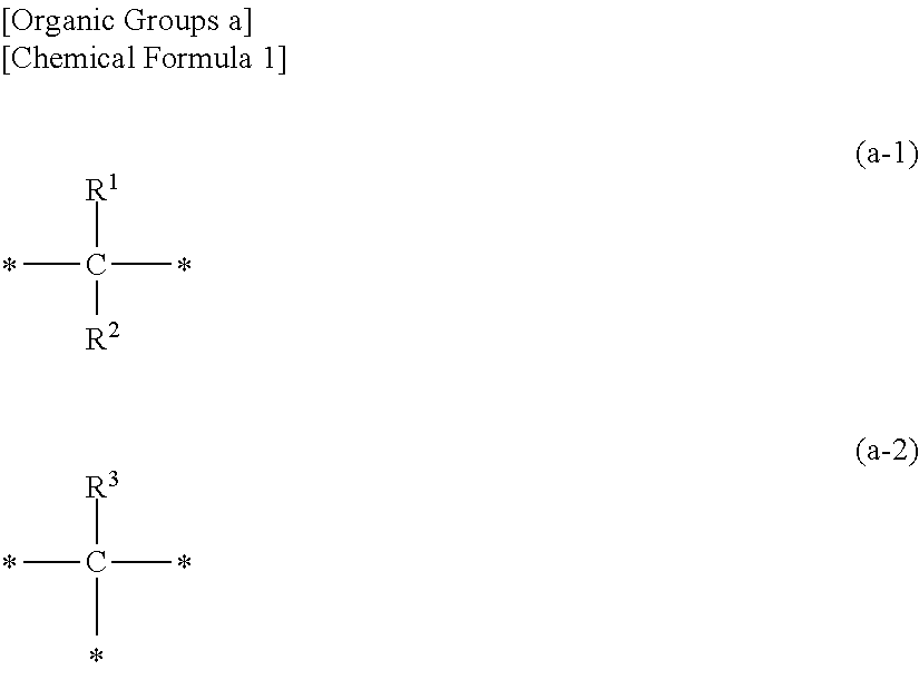
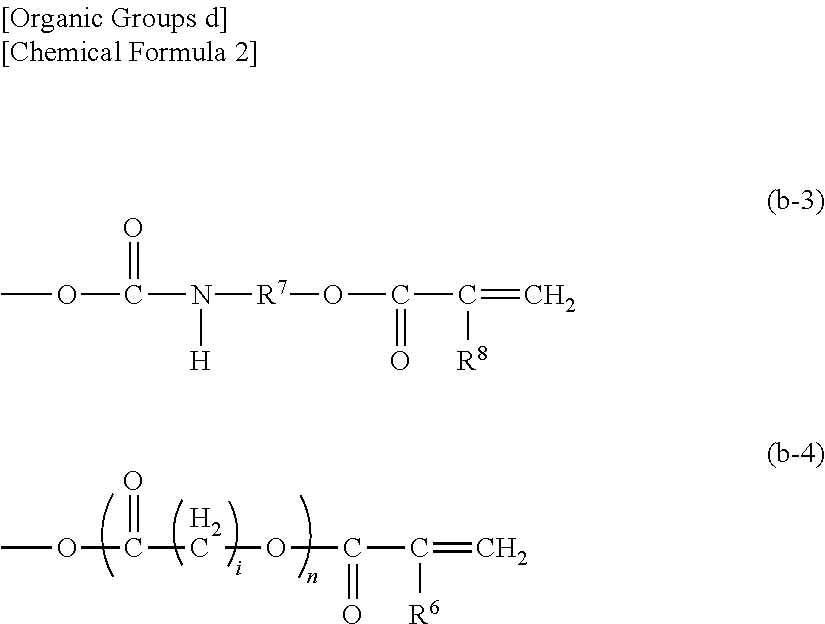
Shown are: a photocurable inkjet ink containing 3 to 60 wt % of a compound (A2) that has a skeleton structure consisting of at least three benzene rings and at least one group selected from the following organic groups a, wherein all bonds between the benzene rings are formed through one of the groups, and that has at least one group selected from the following organic groups d that are bonded to the benzene rings, and 1 to 60 wt % of a compound (B) represented by the following formula (7) or (8); a microlens obtained by photocuring the photocurable inkjet ink; a laminate obtained by forming the microlens on a liquid-repellent cured film; an optical component having the laminate; and an image display device including the optical component.

Description

FIELD OF THE INVENTION[0001]The invention relates to a photocurable inkjet ink suitably used for manufacturing a light guide as a member of a backlight unit built in an optical instrument such as an image display device, etc. More specifically, the invention relates to a photocurable inkjet ink, the photocurable inkjet ink being employed in a microlens that is employed in manufacturing a light guide and also being employed in a liquid-repellent cured film used for controlling a shape of the microlens.DESCRIPTION OF THE RELATED ART[0002]Conventionally, a microlens formed on a light guide for an image display device has been formed by injection molding using a mold. However, when manufacturing various kinds of microlenses in small quantities using this method, it is necessary to remake the mold according to product designs, and an increase in manufacturing steps has become a problem.[0003]In recent years, as a manufacturing method having high design freedom, a method has been proposed...

Claims


Application Information

Patent Timeline
Patent Type & Authority Applications(United States)
IPC IPC(8): C09D11/101F21V8/00G02B1/04G02B1/18C09D4/00C09D11/30
CPCC09D11/101C09D4/00G02B6/0036G02B1/041G02B1/18C09D11/30C08F220/20C08F220/36C08F222/10C09D11/38C08F220/281C08F220/301C08F222/103G02B3/0012B32B2307/418B32B2551/00C08F20/20C08F20/30C08F20/36G02B6/0065C08F220/285G02B3/00
Inventor ONO, KOHEISUGIHARA, KATSUYUKIHIROTA, TAKAYUKI
Owner JNC CORP
Learn More