
Vacuum sponge drainage

a vacuum sponge and sponge technology, applied in the field of vacuum sponge units, can solve problems such as problems such as problematic use and application field of the device, and achieve the effect of simplifying guidan

Active Publication Date: 2016-12-15
LOHMANN & RAUSCHER
View PDF5 Cites 4 Cited by
  • Summary
  • Abstract
  • Description
  • Claims
  • Application Information

AI Technical Summary

Benefits of technology

Enables effective treatment of deeper internal wounds and broader application in the gastrointestinal tract by allowing positioning and monitoring of the sponge system in remote body regions, facilitating complete closure and healing of internal wounds while maintaining continuous drainage and suction.

Problems solved by technology

The inventor has also realized that the field of application of the device in WO 2004 / 041346 A1 is limited in particular to intracorporeal regions that are open on one side only and that it is problematic to use it in channel-like intracorporeal regions which are open on two sides.

Method used


Image

  • Vacuum sponge drainage
  • Vacuum sponge drainage
  • Vacuum sponge drainage

Examples


Embodiment Construction

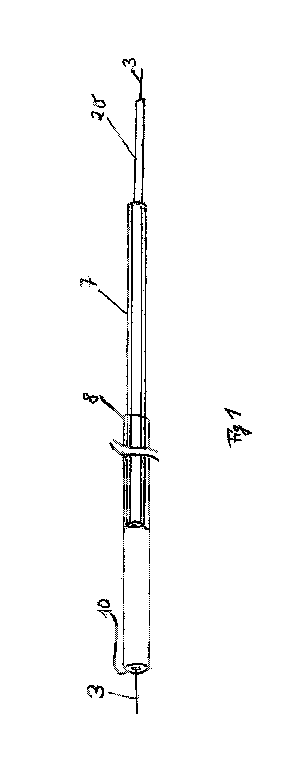
[0073]An embodiment according to the invention is shown in FIGS. 1-7. FIG. 1 is a view showing the arrangement of the complete insertion system. The compressed sponge 10, which is connected to drainage line 20, is received at the distal end of guide sleeve 8. A positioning sleeve 7 is likewise inserted into the guide sleeve via drainage line 20 and can be moved in relation to both the guide sleeve and the drainage line.

[0074]Guide wire 3 is located inside the drainage line. Said guide wire is initially placed endoscopically over a defect, and the entire insertion system can then be advanced over the wire into position. The sponge has an X-ray-proof marker, so that positioning can be carried out and monitored under X-ray surveillance.

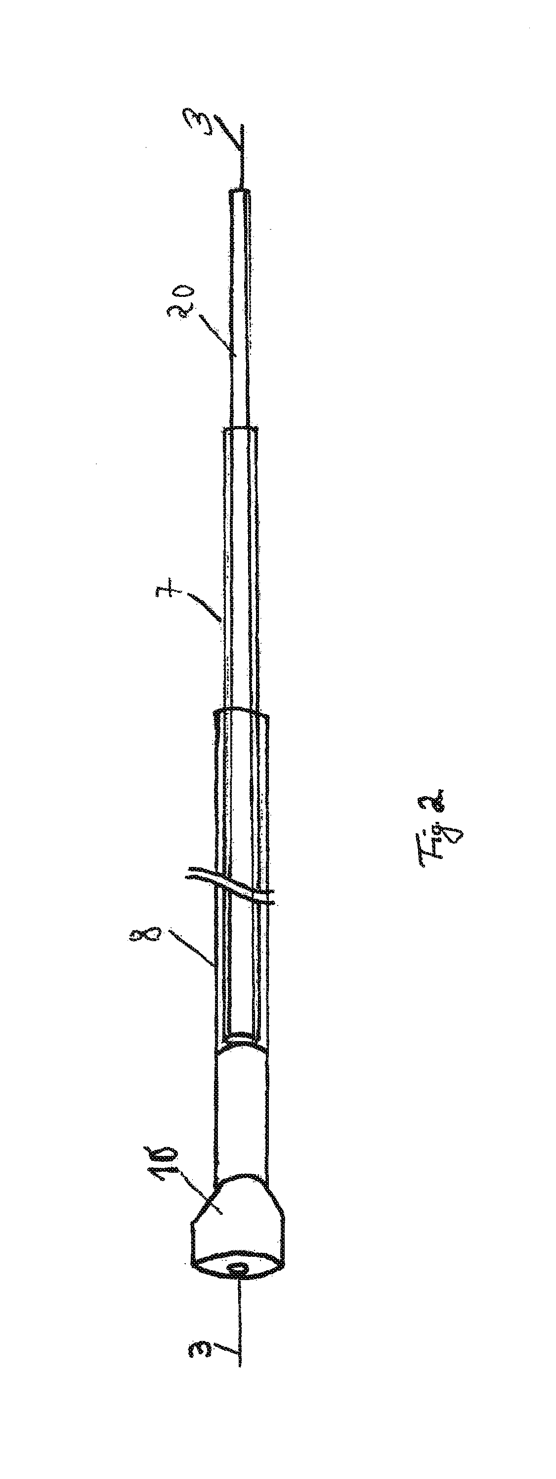
[0075]FIG. 2 shows the commencement of sponge 10 being released. Positioning sleeve 7 and guide sleeve 8 are moved towards each other, thus causing the sponge to emerge from the distal end of the guide sleeve. FIG. 3 shows continued release of the sponge...


PUM

PropertyMeasurementUnit
pressureaaaaaaaaaa
pressuresaaaaaaaaaa
pressuresaaaaaaaaaa

Abstract

The invention relates to a vacuum sponge unit (2) for use in human or animal bodies, comprising a fluid collecting member (10), in particular a sponge unit, and a fluid communication member (20), in particular a drainage tube, which is disposed at least partially in the fluid collecting member (10) and is connected in fluidic communication to the fluid collecting member (10). In order to improve known devises, the inventions proposed developing the vacuum sponge unit (2) such that the fluid collecting member (10) has a channel (11) for guiding a guide member (3), in particular a guide wire, and / or a delivery member (4), in particular a probe unit and / or an endoscope, through the fluid collecting member (10).

Description

CROSS-REFERENCE TO RELATED APPLICATIONS[0001]This application claims priority to and is a divisional of U.S. patent application Ser. No. 13 / 499,438 filed on Oct. 12, 2012, which is a U.S. National Stage of International Application Number PCT / EP2010 / 060671 filed on Jul. 22, 2010 which was published on Apr. 7, 2011 under International Publication number WO 2011 / 038949, and which claims priority to German patent application 102009043472.0 filed on Sep. 30, 2009; German patent application 102009057374.7 filed on Dec. 9, 2009; German patent application 102010013271.3 filed on Mar. 29, 2010; German patent application 102010013439.2 filed on Mar. 30, 2010, German patent application 102010013849.5 filed on Apr. 1, 2010 and German patent application 102010013848.7 filed on Apr. 1, 2010, all of which are incorporated herein by reference in their entirety.TECHNICAL FIELD[0002]The invention relates to a vacuum sponge unit for use in human or animal bodies, comprising a fluid collecting member,...

Claims


Application Information

Patent Timeline
Patent Type & Authority Applications(United States)
IPC IPC(8): A61M1/00A61F13/36A61B1/12A61B1/273A61B17/22A61M25/09A61B90/00A61B1/00
CPCA61M1/0084A61M1/0088A61B90/39A61F13/36A61B1/00135A61B1/2736A61M2210/1042A61M25/09A61B1/12A61M1/0023A61B2090/3966A61M2210/1021A61B17/22A61M27/00Y10T29/49826A61M1/85A61M1/92A61M1/916A61M1/94
Inventor LOSKE, GUNNARSCHORSCH, TOBIAS
Owner LOHMANN & RAUSCHER
Learn More