Semiconductor device, display module, and electronic device
a technology of semiconductor devices and display modules, applied in semiconductor devices, digital storage, instruments, etc., can solve the problems of increasing the degree of wiring congestion in the driver's ic, reducing display quality, etc., and achieve the effect of increasing the degree of freedom of choi
- Summary
- Abstract
- Description
- Claims
- Application Information
AI Technical Summary
Benefits of technology
Problems solved by technology
Method used
Image
Examples
embodiment 1
[0042]In this embodiment, an example of a semiconductor device functioning as a driver IC will be described.
[0043]In this specification and the like, a semiconductor device means any device that can function by utilizing semiconductor characteristics; thus, a driver IC composed of semiconductor elements such as transistors and a display device including the driver IC are included in the category of the semiconductor device.
[0044]
[0045]A semiconductor device of one embodiment of the present invention is applied to a driver IC functioning as a source driver, in the following description. Therefore, a source driver and a driver IC are each also referred to as a semiconductor device.
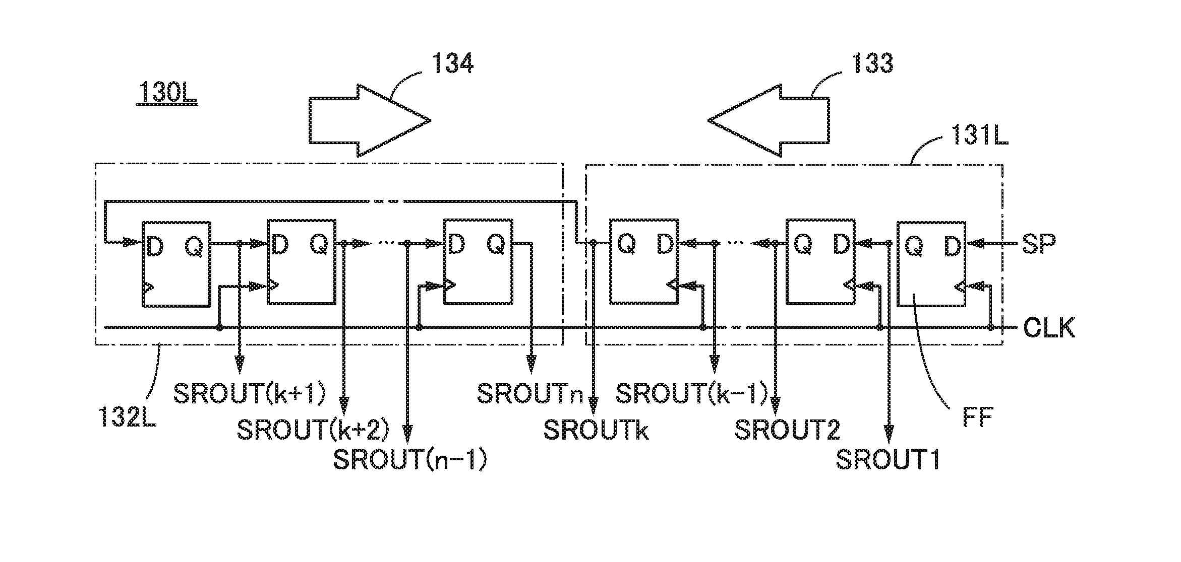
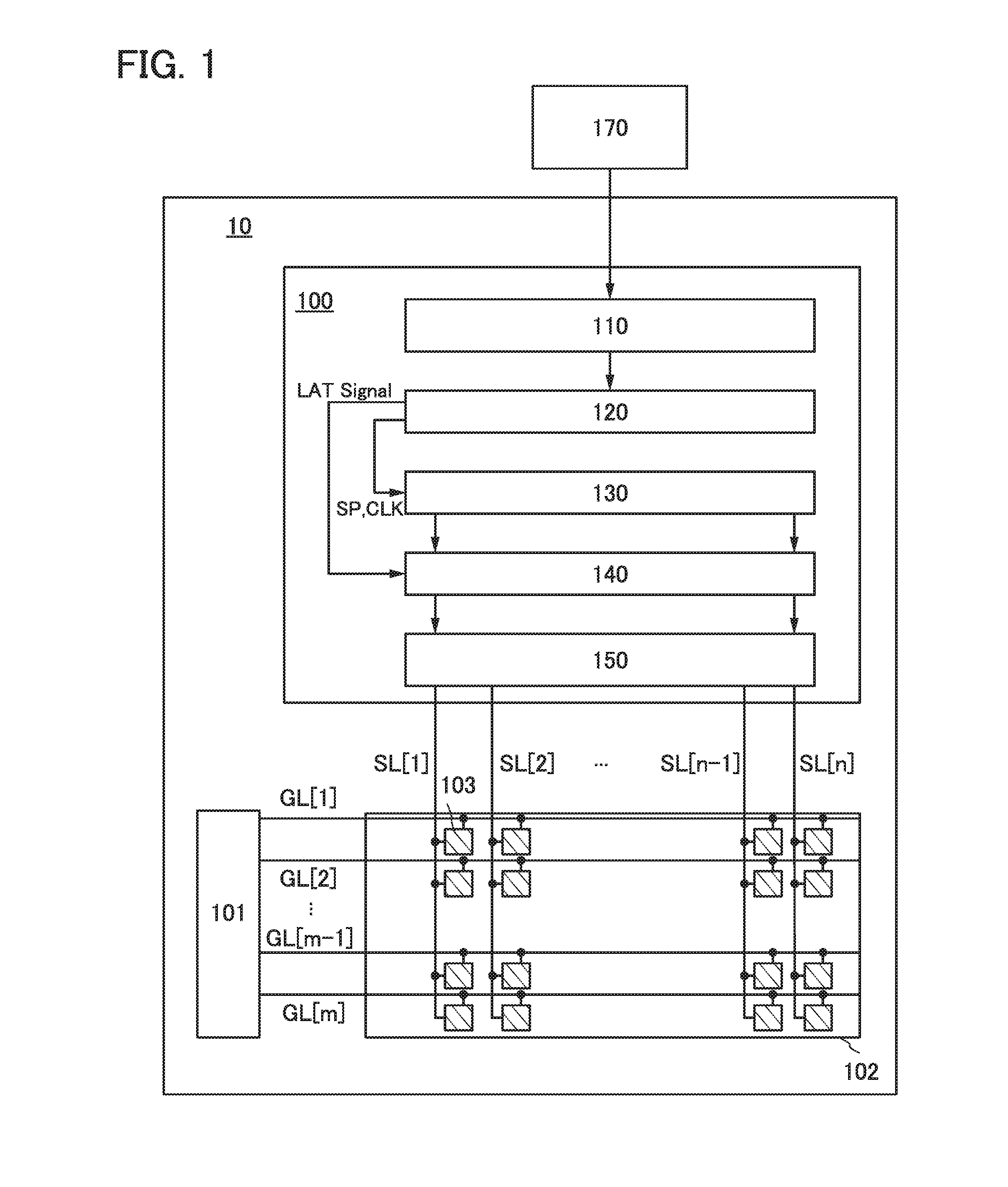
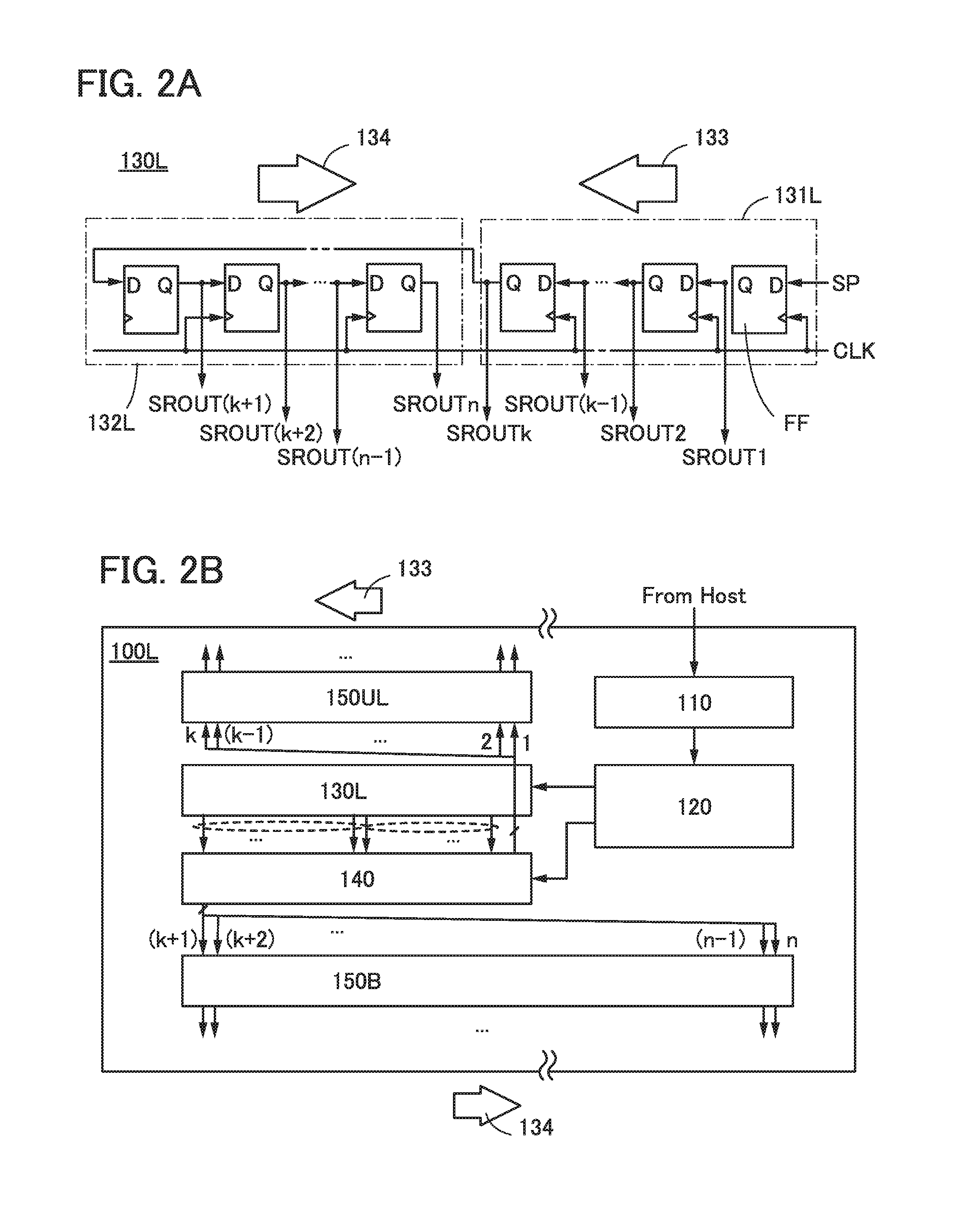
[0046]FIG. 1 is a block diagram of a display device 10 including a source driver. The display device 10 includes a source driver 100, a gate driver 101, and a display portion 102.
[0047]The display portion 102 includes pixels 103 arranged in a matrix. Each of the pixels 103 is connected to one of source lines...
embodiment 2
[0095]In this embodiment, an example of a circuit configuration of the shift register described in the above embodiment and an example of a circuit configuration of a pixel in the display portion described in the above embodiment will be described.
[0096]FIGS. 8A and 8B illustrate, as one example, a circuit configuration of a static shift register including a plurality of stages of pulse output circuits.
[0097]In the shift register illustrated in FIGS. 8A and 8B, a plurality of pulse output circuits FFs are connected in cascade. The plurality of stages of pulse output circuits FFs are connected to wirings through which a clock signal (CLK1) and a clock signal (CLK2) are transmitted. The pulse output circuit FF in the first stage is connected to a wiring through which a start pulse (SP) is transmitted. Output signals SROUT1 to SROUTn are output from the plurality of stages of pulse output circuits FFs.
[0098]The pulse output circuit FF includes, as illustrated in FIG. 8B, a switch 311, ...
embodiment 3
[0108]In this embodiment, an example of a cross-sectional structure of a semiconductor device in one embodiment of the present invention will be described with reference FIG. 10.
[0109]In the semiconductor device described in the above embodiment, the circuits such as the shift register circuit can be formed using a transistor including silicon. As silicon, polycrystalline silicon, microcrystalline silicon, or amorphous silicon can be used. Note that an oxide semiconductor or the like can be used instead of silicon.
[0110]FIG. 10 is a schematic cross-sectional view of a semiconductor device of one embodiment of the present invention. The semiconductor device in the schematic cross-sectional view of FIG. 10 includes an n-channel transistor and a p-channel transistor that contain a semiconductor material (e.g., silicon).
[0111]An n-channel transistor 510 includes a channel formation region 501 in a substrate 500 containing a semiconductor material, low-concentration impurity regions 502 ...
PUM
 Abstract
Description
Claims
Application Information
 - R&D
- Intellectual Property
- Life Sciences
- Materials
- Tech Scout
- Unparalleled Data Quality
- Higher Quality Content
- 60% Fewer Hallucinations
Browse by: Latest US Patents, China's latest patents, Technical Efficacy Thesaurus, Application Domain, Technology Topic, Popular Technical Reports.
© 2025 PatSnap. All rights reserved.Legal|Privacy policy|Modern Slavery Act Transparency Statement|Sitemap|About US| Contact US: help@patsnap.com


