
Electric power convertion apparatus and method of operating the same

a technology of electric power conversion and electric power, which is applied in the direction of power conversion systems, dc-dc conversion, instruments, etc., can solve the problems of reducing the operation efficiency of a system, affecting the operation efficiency of the system, so as to achieve wide voltage range, wide voltage range, and high electric power conversion efficiency

Active Publication Date: 2016-12-01
LSIS CO LTD
View PDF5 Cites 20 Cited by
  • Summary
  • Abstract
  • Description
  • Claims
  • Application Information

AI Technical Summary

Benefits of technology

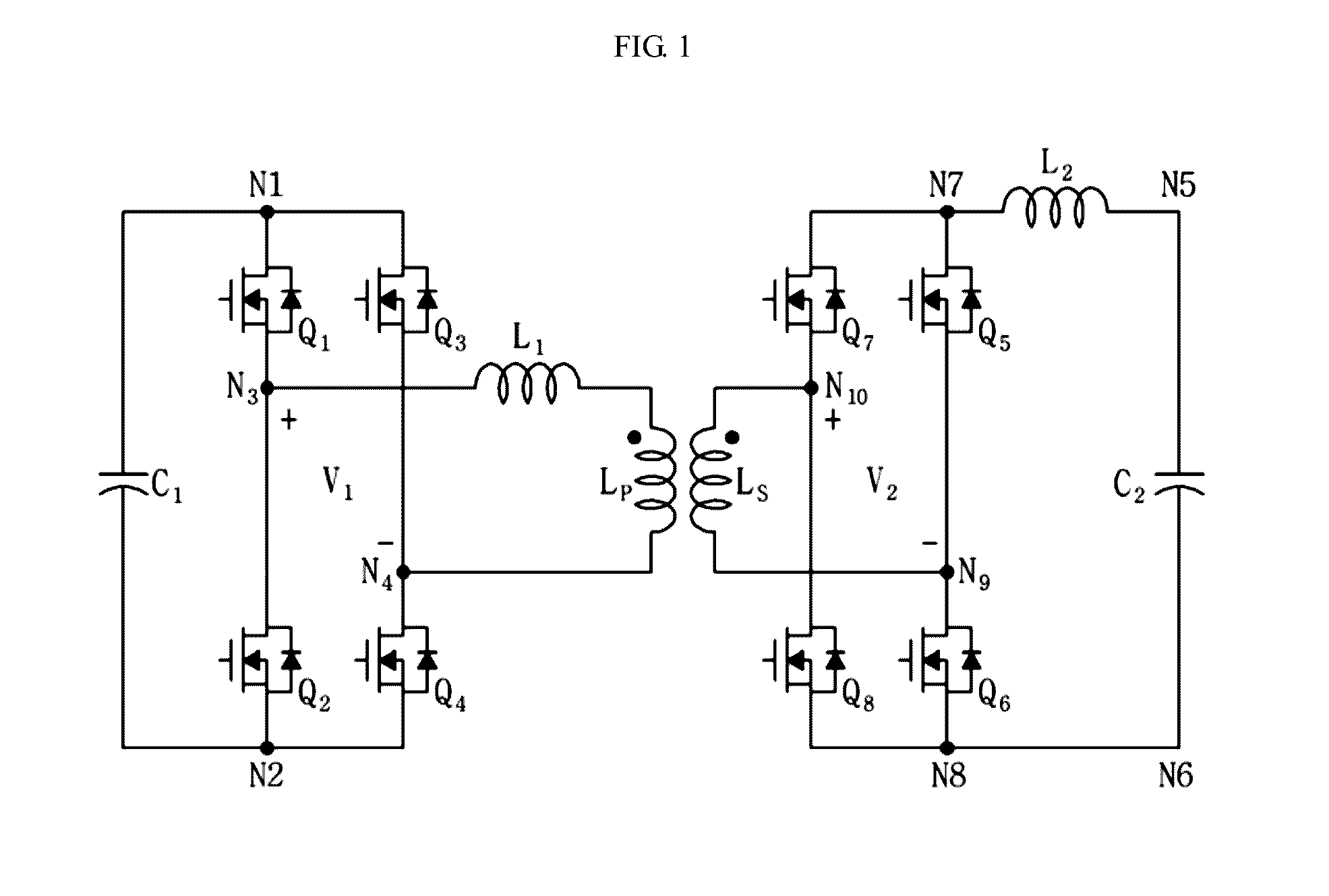
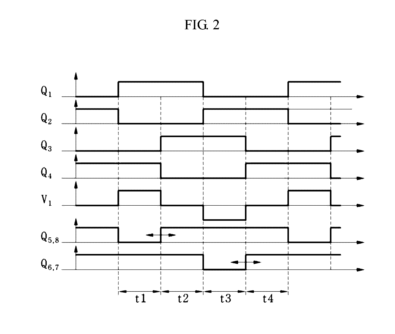
The electric power conversion apparatus described in this patent changes the way it modifies a switching signal based on the output power level. This has two main benefits. Firstly, it simplifies the control method, which makes it easier to deliver power in a wider range of voltages. Secondly, it improves the efficiency of power conversion over a wider range of voltages. Additionally, the apparatus addresses the issue of sudden changes in output voltage and current that can occur when different modulation methods are used.

Problems solved by technology

The phase control method has disadvantages in which a safety problem may occur and an operation efficiency of a system may be lowered because a circulation current is increased when an output electric power is decreased or an input / output voltage ratio is increased.
And, in comparison with the phase control method, the PWM method has advantages of high efficiency and high performance, but it also has a disadvantage in which a control is complicated.
In this case, since a variety of control variables such as a first switching signal, a second switching signal, and a phase difference therebetween are required for controlling the first converter and the second converter, there is a disadvantage in which a control operation is considerably complicated.
Here, the dual PWM method has a disadvantage in which high efficiency may not be obtained at a low electric power if an operation condition is not suitably satisfied.
Lastly, the optimum modulation method has disadvantages in which an acquiring of an optimized modulation value is difficult and a control operation is considerably complicated the same as that of the dual PWM method.

Method used


Image

  • Electric power convertion apparatus and method of operating the same
  • Electric power convertion apparatus and method of operating the same
  • Electric power convertion apparatus and method of operating the same

Examples


Embodiment Construction

[0057]Advantages and features of the present disclosure and methods of accomplishing the same may be understood more readily with reference to the following description of exemplary embodiments and the accompanying drawings. However, the present disclosure is not limited to the embodiments set forth herein, and it will be implemented in different types. Also, these embodiments are provided to completely describe the present disclosure, and to teach a person skilled in the art by fully conveying the concept of the disclosure, and the present disclosure will only be defined by the appended claims. The same reference numerals throughout the specification refer to the same elements.

[0058]In the following description of the present disclosure, if a detailed description of known functions and configurations is determined to obscure the interpretation of embodiments of the present disclosure, the detailed description thereof will be omitted. And, all terms used hereinafter are selected by ...


PUM


Abstract

Some embodiments include an electric power conversion apparatus, which may include a transformer, a first converter connected to a primary side of the transformer, a second converter connected to a secondary side of the transformer, a first capacitor connected to the first converter, a second capacitor connected to the second converter, and a control unit for controlling the first converter and the second converter, wherein the control unit may determine operation ranges with respect to a plurality of modulation methods, may determine a modulation method including an output electric power value of the electric power conversion apparatus among the operation ranges of the plurality of modulation methods, and may output control signals of the first converter and the second converter based on the determined modulation method, wherein the control signals correspond to an instruction value.

Description

CROSS REFERENCE TO RELATED APPLICATION[0001]This application claims the benefit of Korean Patent Application No. 10-2015-0076170, filed on May 29, 2015, entitled “ELECTRIC POWER CONVERTION APPARATUS AND METHOD OF OPERATING THE SAME”, which is hereby incorporated by reference in its entirety.BACKGROUND1. Technical Field[0002]The present disclosure relates to an electric power conversion apparatus, and more particularly, to an electric power conversion apparatus capable of outputting a switching signal by applying a different modulation method according to an electric power output from an electric power conversion apparatus transmitting an electric power bidirectionally, and a method of operating the same.2. Description of the Related Art[0003]For the purpose of supplying energy to an electronic circuit requiring a relative high voltage or using energy in an application field in connection with a system, it may be necessary to boost an input voltage to a high voltage. In addition, dep...

Claims


Application Information

Patent Timeline
Patent Type & Authority Applications(United States)
IPC IPC(8): H02M3/335H02M1/08
CPCH02M3/33546H02M2001/0009H02M1/08H02M3/33523H02M3/33584H02M1/0009
Inventor YOO, ANNOCHO, YOUNG-HOONBYEN, BYENG-JOO
Owner LSIS CO LTD
Learn More