
Power control method, device and communication terminal for radio frequency power amplifier

a power amplifier and power control technology, applied in amplifiers, instruments, electrical apparatuses, etc., can solve the problems of reducing the power spectrum characteristic, generating noise, and reducing the power-added efficiency of the rf pa at a low power, so as to reduce the noise of the system, improve the power-added efficiency of the rf pa, and widen the effect of the power-added efficiency

Active Publication Date: 2019-08-27
BEIJING VANCHIP TESTING TECH CO LTD
View PDF8 Cites 10 Cited by
  • Summary
  • Abstract
  • Description
  • Claims
  • Application Information

AI Technical Summary

Benefits of technology

The present invention improves the efficiency of an RF power amplifier (RF PA) at multiple power levels and voltage ranges. This reduces the working current of the RF PA, which decreases system noise. Additionally, a voltage sensing module helps improve the transient switch spectrum and working efficiency of the RF PA at its rated power.

Problems solved by technology

As a result, efficiency of the RF PA at a low power is very poor.
Therefore, it is still a challenge to design an RF PA that can efficiently operate within respective power ranges.
Apparently, because the two voltages are separate rather than continuous, when switching is performed between the two voltages, a sudden change of an output power will occur, which may degrade a power spectrum characteristic and generate noise.
A challenge of the solution is to design a feedback circuit that is stable and has an enough bandwidth on each power level.
Although by means of the solution, power-added efficiency at a low power is improved, a switch spectrum and a harmonic wave may easily deteriorate at a high power, especially at a high power and a low supply voltage.
Therefore, linearly controlling a base voltage by using a power control signal while satisfying a requirement of the burst mask, so as to further improve efficiency of an RF PA without affecting a switch spectrum characteristic, is a technical problem urgently needs to be resolved.

Method used


Image

  • Power control method, device and communication terminal for radio frequency power amplifier
  • Power control method, device and communication terminal for radio frequency power amplifier
  • Power control method, device and communication terminal for radio frequency power amplifier

Examples


Embodiment Construction

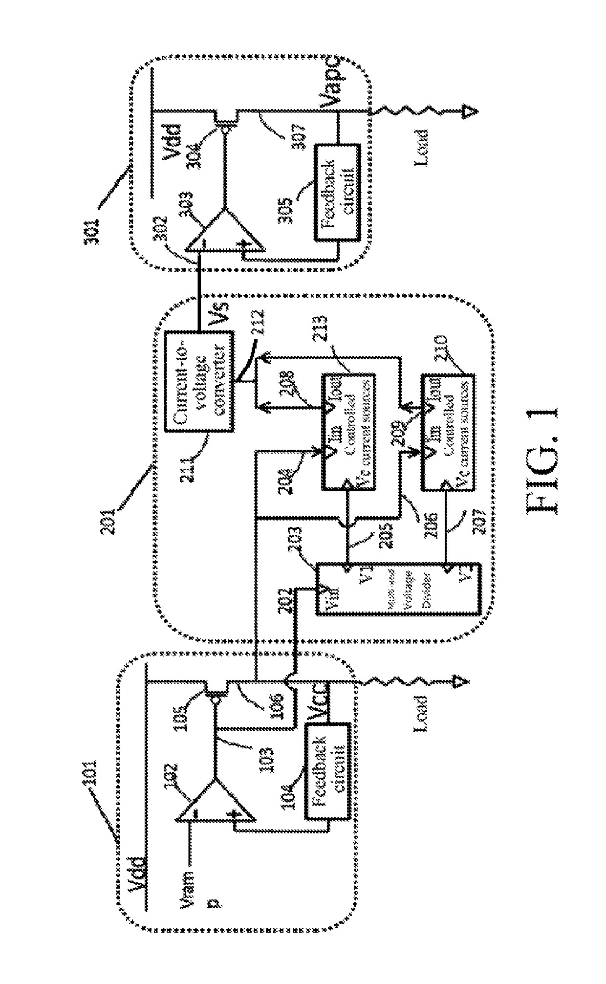
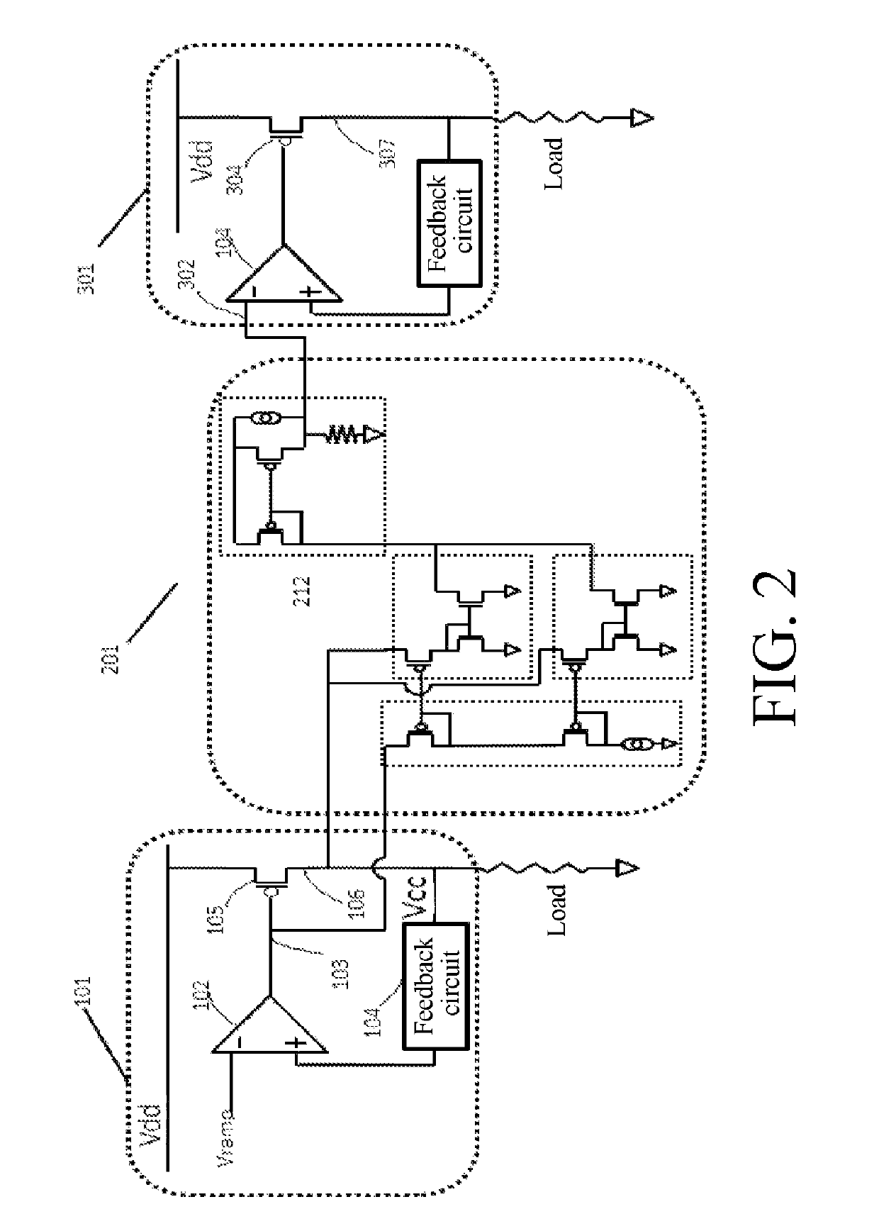
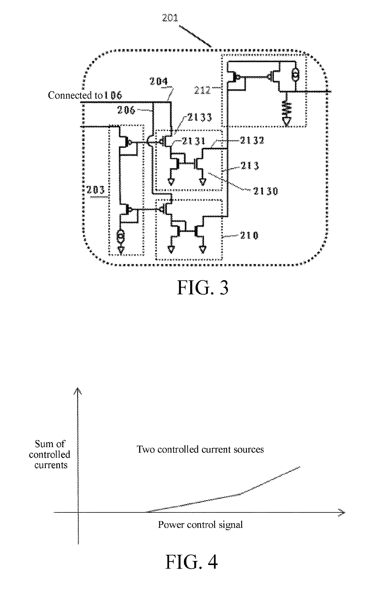
[0039]The following further describes technical content of the present invention in details with reference to the accompanying drawings and specific embodiments.

[0040]To achieve an objective of optimizing power-added efficiency of an RF PA at multiple power levels and within a broad supply voltage range, the present invention first provides a power control method for an RF PA. The method mainly includes the following steps:

[0041]1. reading a supply voltage signal and a power control signal, and generating an amplified signal having a linear relationship with the power control signal;

[0042]2. generating one or more controlled currents according to the amplified signal and saturation degree information, combining the controlled currents, and converting a combined total current into a voltage; and

[0043]3. performing linear voltage regulation on the converted voltage, and generating a base control voltage of the RF PA.

[0044]Technical details about the power control method are described ...


PUM


Abstract

Disclosed is a power control method for a radio frequency power amplifier, comprising the following steps: S1. reading a power source voltage signal and a power control signal and generating an amplified signal having a linear relationship with the power control signal; S2. according to the amplified signal and saturation information, generating one or more controlled currents, merging each controlled current, and converting the merged total current into voltage; S3. Conducting linear voltage regulation on the converted voltage and generating a base control voltage of the radio frequency power amplifier. The present invention dynamically monitors the saturation information of a pass element to change the base voltage of the radio frequency power amplifier, thus improving additional power efficiency of the radio frequency power amplifier at multiple power level and over a large power source voltage range, and improving the properties of the radio frequency switch thereof.

Description

BACKGROUNDTechnical Field[0001]The present invention relates to the field of wireless communications technologies, to a power control method for a radio frequency power amplifier (RF PA), and also to a power control device for implementing the power control method and a communication terminal including the power control device.Related Art[0002]An RF PA is widely applied to communication terminals such as mobile phones. In a pre-stage circuit of a transmitter, a power of a radio frequency signal generated by a modulation and oscillation circuit is very low, and an RF PA needs to perform a series of amplifications in a buffer stage, an intermediate amplification stage, and a final power amplification stage to obtain a sufficient radio frequency power, so as to feed the power to the antenna to radiate it. In this process, accurate power control is critical to ensuring normal use of a communication terminal.[0003]At present, there are various mobile communications standards or wireless ...

Claims


Application Information

Patent Timeline
Patent Type & Authority Patents(United States)
IPC IPC(8): H03G3/10H03F1/02H03G3/30G05F1/56G05F1/46
CPCH03F1/0216H03F2200/555H03G3/3047G05F1/468G05F1/56H03F1/0227H03F1/025H03F1/0277
Inventor LIU, XIDA
Owner BEIJING VANCHIP TESTING TECH CO LTD
Learn More