Wide Angle Imaging Directional Backlights

a wide angle imaging and backlight technology, applied in the field of light guides, can solve the problems of limiting the viewing freedom of the display, increasing the level of image crosstalk, and non-uniform viewing windows, and achieve the effects of saving power operation, high luminance operation, and large area

Active Publication Date: 2016-12-01
REALD SPARK LLC
View PDF0 Cites 62 Cited by
  • Summary
  • Abstract
  • Description
  • Claims
  • Application Information

AI Technical Summary

Benefits of technology

Directional backlights offer control over the illumination emanating from a display by using modulation of LED light sources. This technology can achieve single person viewing for security functions, high electrical efficiency, alternating left and right eye viewing for time sequential stereoscopic and autostereoscopic display, and low cost. However, there is a problem with the appearance of dark outer portions for off-axis viewing positions, which reduces the area of the waveguide that can be used to illuminate the display. The patent proposes a solution to reduce the appearance of the dark outer portions and make more of the area of the waveguide available for illumination.

Problems solved by technology

Gaps between the pixels, for example for electrodes, typically produce non-uniform viewing windows.
Undesirably such displays exhibit image flicker as an observer moves laterally with respect to the display and so limit the viewing freedom of the display.
Such flicker can be reduced by defocusing the optical elements; however such defocusing results in increased levels of image cross talk and increases visual strain for an observer.

Method used


Image

  • Wide Angle Imaging Directional Backlights
  • Wide Angle Imaging Directional Backlights
  • Wide Angle Imaging Directional Backlights

Examples


Embodiment Construction

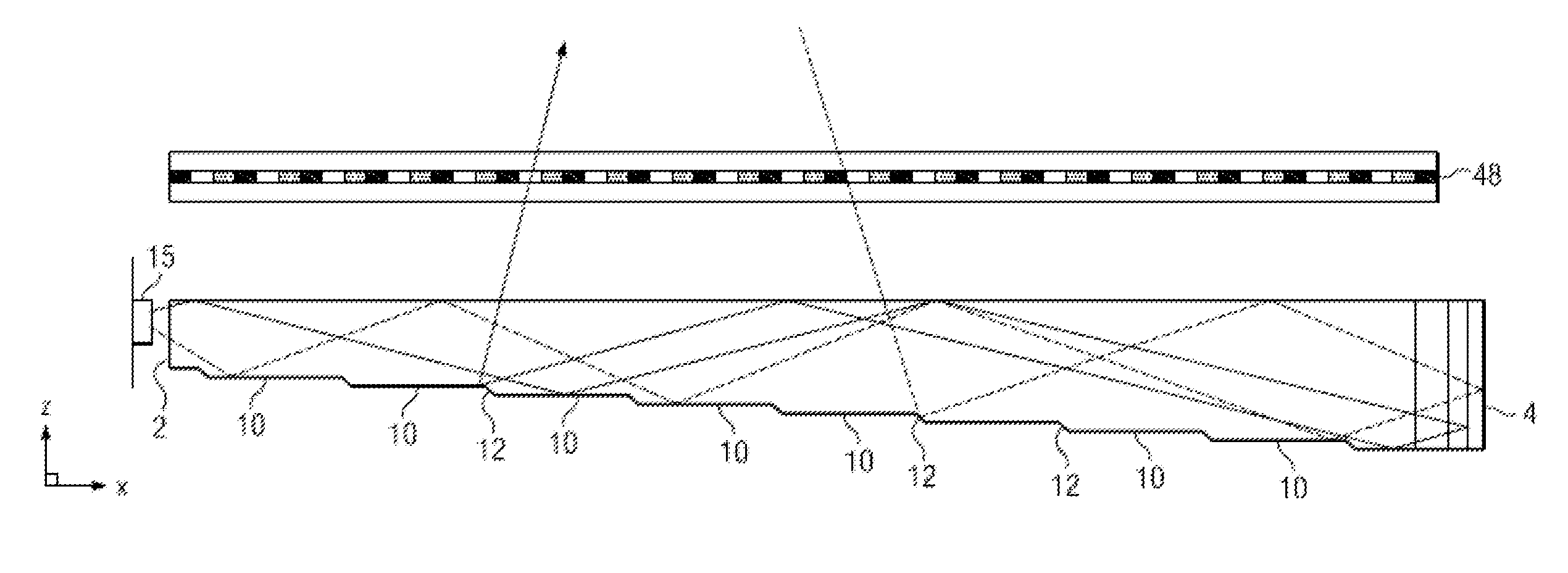
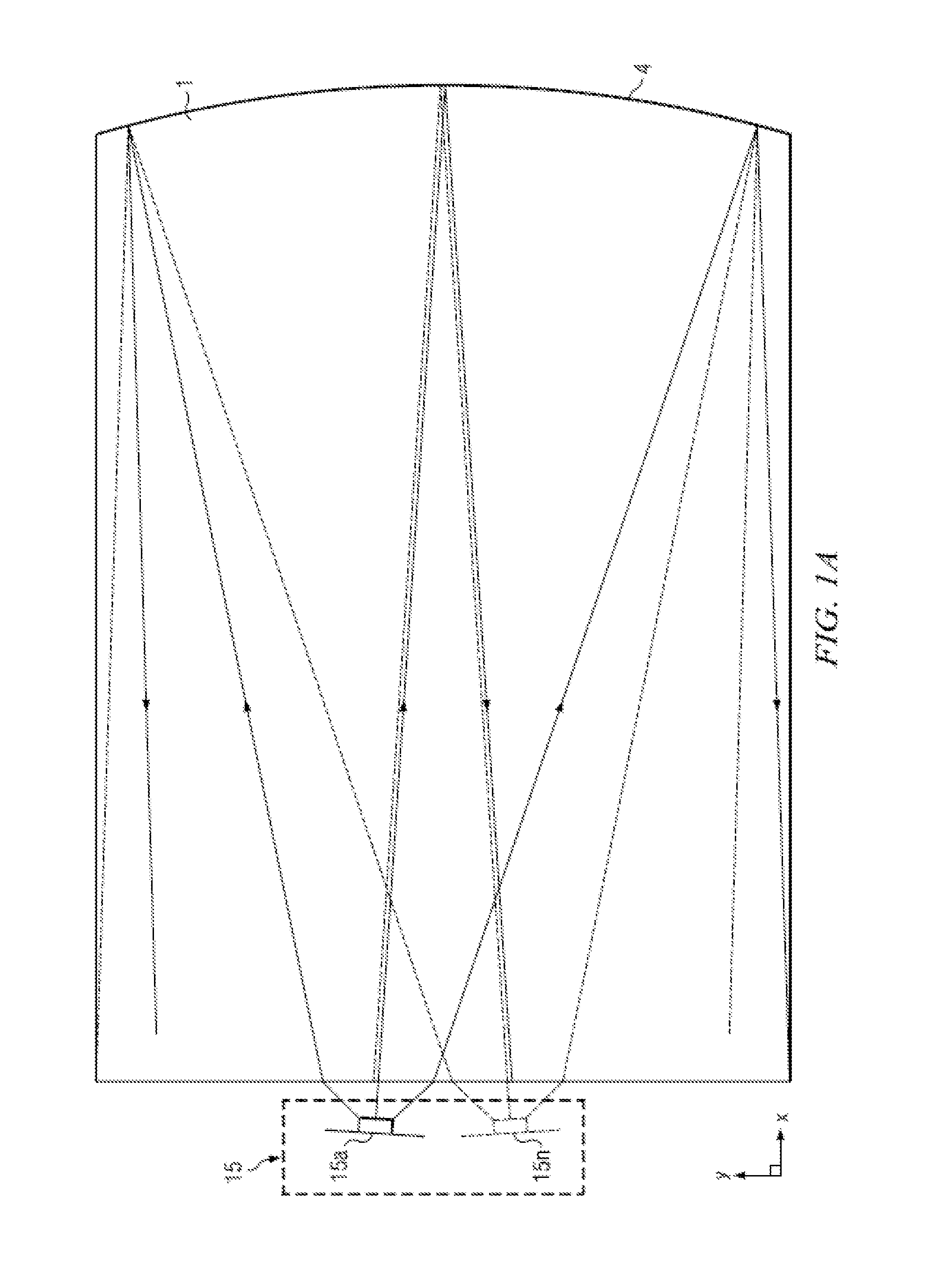
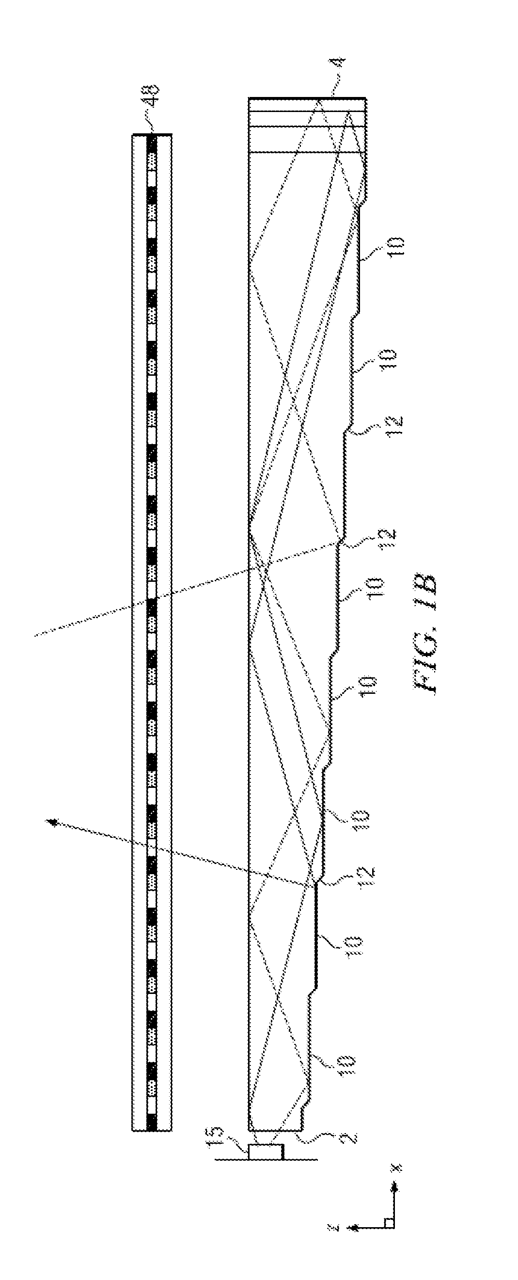
[0113]Time multiplexed autostereoscopic displays can advantageously improve the spatial resolution of autostereoscopic display by directing light from all of the pixels of a spatial light modulator to a first viewing window in a first time slot, and all of the pixels to a second viewing window in a second time slot. Thus an observer with eyes arranged to receive light in first and second viewing windows will see a full resolution image across the whole of the display over multiple time slots. Time multiplexed displays can advantageously achieve directional illumination by directing an illuminator array through a substantially transparent time multiplexed spatial light modulator using directional optical elements, wherein the directional optical elements substantially form an image of the illuminator array in the window plane.

[0114]The uniformity of the viewing windows may be advantageously independent of the arrangement of pixels in the spatial light modulator. Advantageously, such ...


PUM


Abstract

An imaging directional backlight apparatus including a waveguide, a light source array, for providing large area directed illumination from localized light sources. The waveguide may include a stepped structure, in which the steps may further include extraction features optically hidden to guided light, propagating in a first forward direction. Returning light propagating in a second deflected direction may be refracted, diffracted, or reflected by the features to provide discrete illumination beams exiting from the top surface of the waveguide. Viewing windows are formed through imaging individual light sources from the side of the waveguide and hence defines the relative positions of system elements and ray paths. A directional backlight with small footprint and low thickness may be provided.

Description

CROSS-REFERENCE TO RELATED APPLICATIONS[0001]This application claims priority to U.S. Provisional Patent Appl. No. 62 / 167,203 entitled “Wide angle imaging directional backlights” filed May 27, 2015 (Attorney Ref. No. 384000) and U.S. Provisional Patent Appl. No. 62 / 167,185 entitled “Wide angle imaging directional backlights,” filed May 27, 2015 (Attorney Ref. No. 379000B), both of which are herein incorporated by reference in their entireties.TECHNICAL FIELD[0002]This disclosure generally relates to illumination of light modulation devices, and more specifically relates to light guides for providing large area illumination from localized light sources for use in 2D, 3D, and / or autostereoscopic display devices.BACKGROUND[0003]Spatially multiplexed autostereoscopic displays typically align a parallax component such as a lenticular screen or parallax barrier with an array of images arranged as at least first and second sets of pixels on a spatial light modulator, for example an LCD. Th...

Claims


Application Information

Patent Timeline
IPC IPC(8): F21V8/00
CPCG02B6/0055G02B6/0033G02B6/0068G02B6/0048G02B6/0016G02B6/0038G02B6/0091
Inventor ROBINSON, MICHAEL G.RAMSEY, ROBERT A.WOODGATE, GRAHAM J.
Owner REALD SPARK LLC
Why Eureka
Try Eureka