
Inertial navigation unit enhaced with atomic clock

a technology of atomic clocks and navigation units, applied in satellite radio beaconing, measurement devices, instruments, etc., can solve the problems of increasing the error rate of location solutions, affecting the accuracy of atomic clocks, and affecting the accuracy of gnss receivers. achieve the effect of low drift rate and capable navigation system

Inactive Publication Date: 2016-12-01
ROBOTIC RES OPCO LLC
View PDF9 Cites 24 Cited by
  • Summary
  • Abstract
  • Description
  • Claims
  • Application Information

AI Technical Summary

Benefits of technology

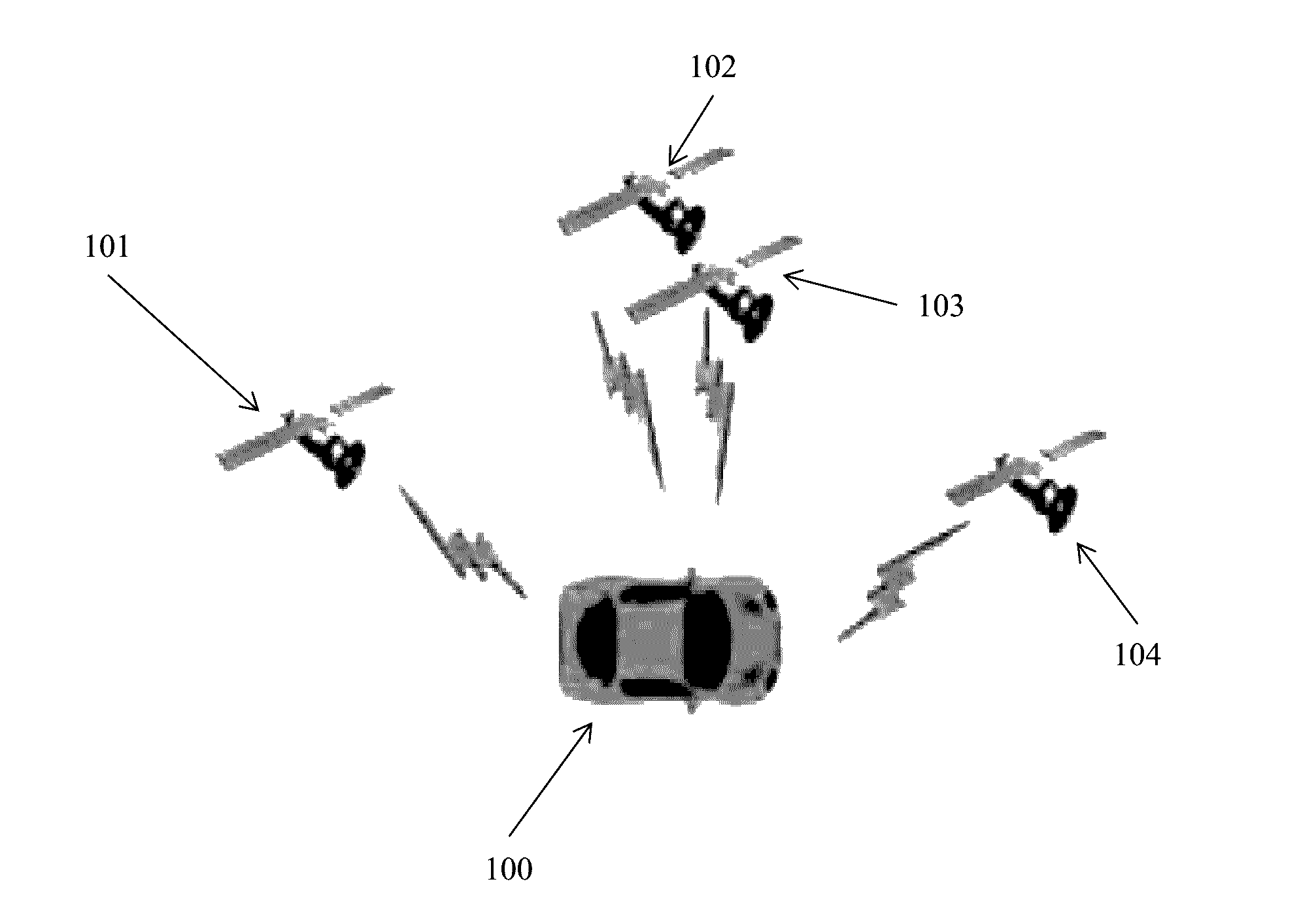
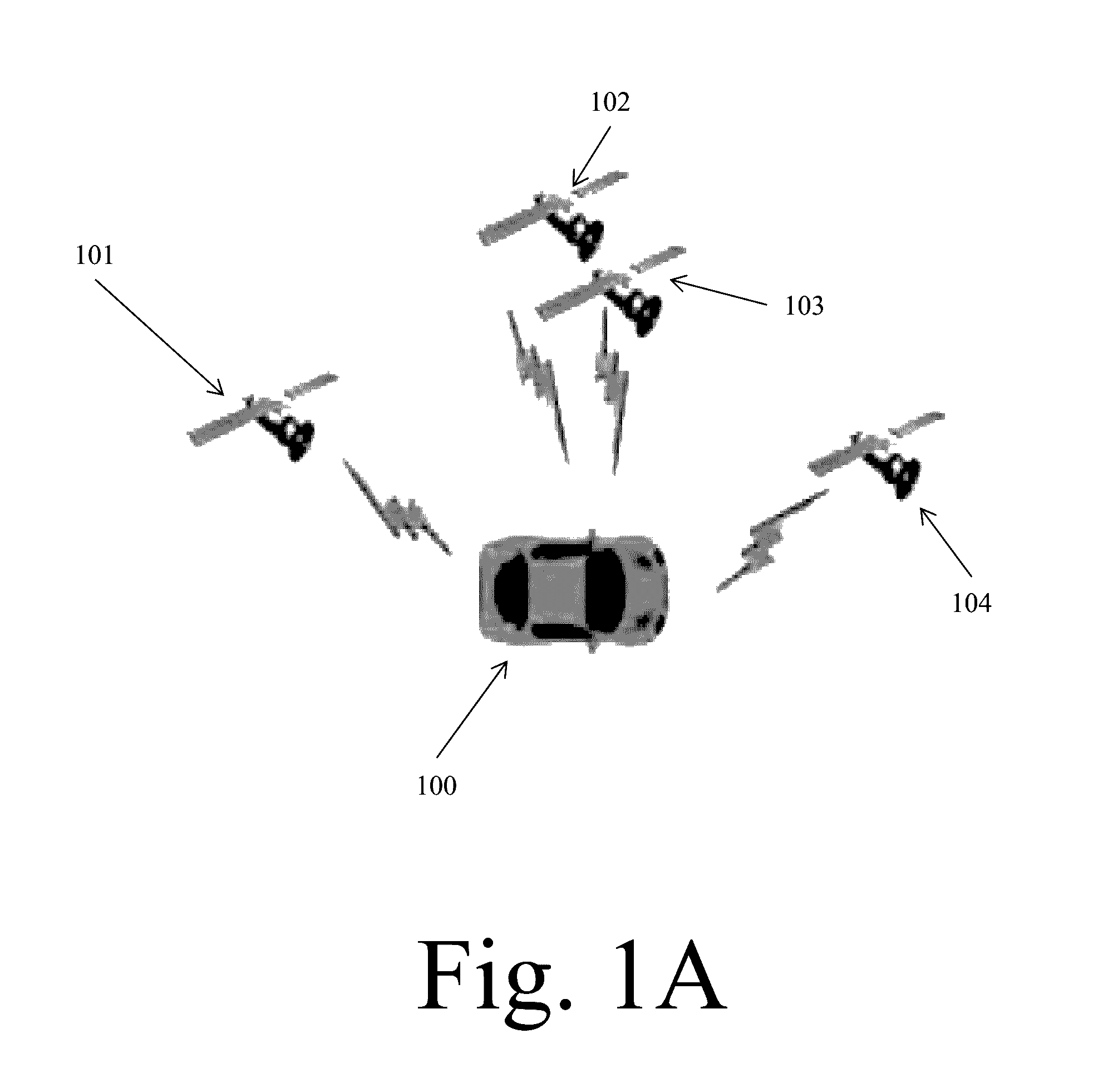
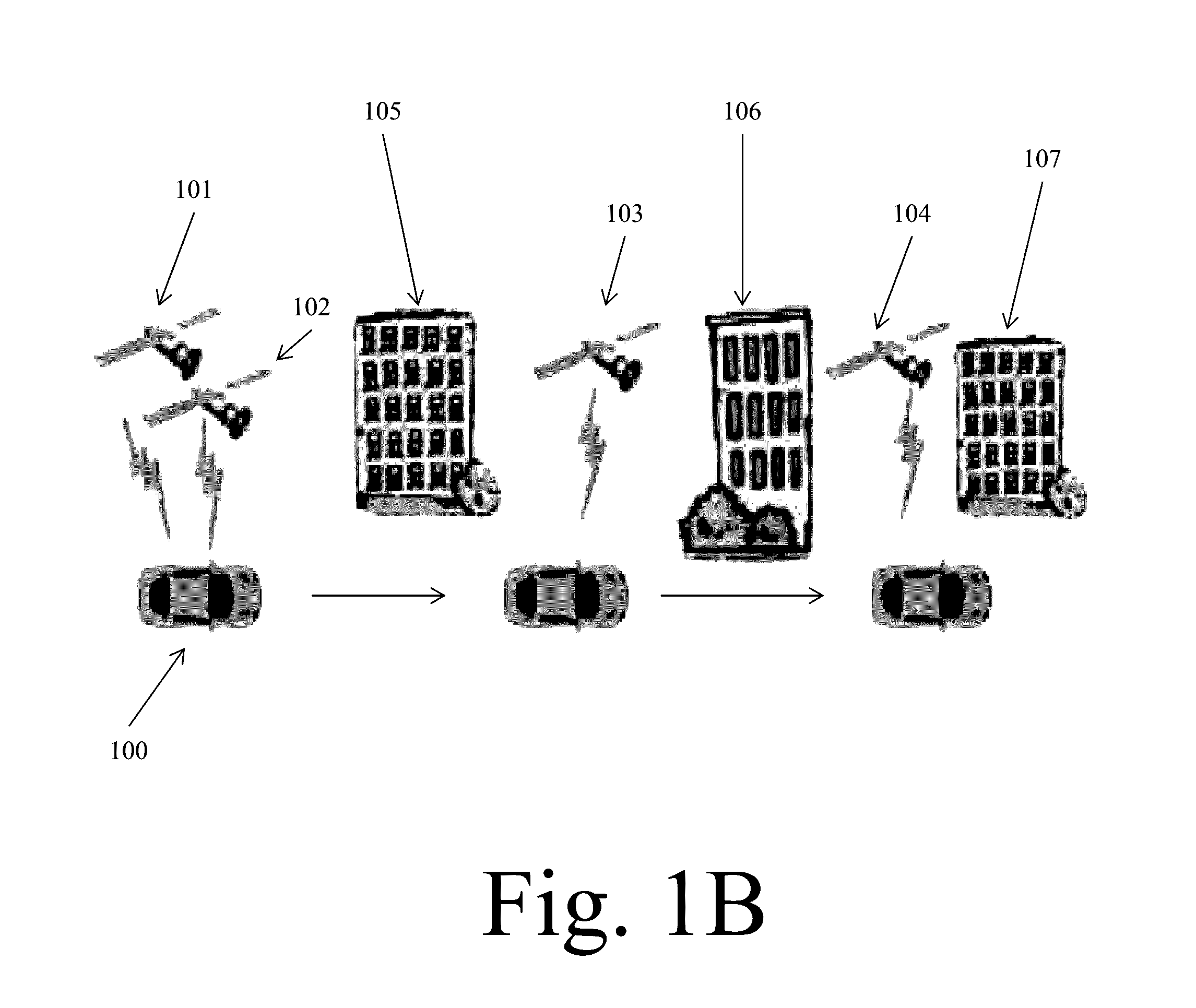
The present invention is a navigation system that uses an atomic clock and GNSS receiver along with inertial sensors. This system can produce a lock even in urban scenarios where parts of the sky are blocked at different times. The accurate time tags provided by the atomic clock make the navigation system much more capable.

Problems solved by technology

While the satellites have accurate atomic clocks, most modern GNSS receivers use less accurate quartz clock.
Quartz clocks—though accurate for most applications—have significant drift when used to measure the minute times required to localize by these signals (travelling close to the speed of light).
When compared to the speed of light, quartz clocks can drift as much as 150 m / s, and therefore, waiting one second between these four measurements can add 150 m to the error of the location solution.
Unfortunately, this means that in order to “get a lock,” conventional GNSS systems need to have full view of at least four GNSS satellites at a given moment of time.
This is relatively easy to do in open areas but it is significantly harder in big cities, where occlusions can mask significant areas of the sky.

Method used


Image

  • Inertial navigation unit enhaced with atomic clock
  • Inertial navigation unit enhaced with atomic clock
  • Inertial navigation unit enhaced with atomic clock

Examples


Embodiment Construction

[0024]In the following detailed description of the invention of exemplary embodiments of the invention, reference is made to the accompanying drawings (where like numbers represent like elements), which form a part hereof, and in which is shown by way of illustration specific exemplary embodiments in which the invention may be practiced. These embodiments are described in sufficient detail to enable those skilled in the art to practice the invention, but other embodiments may be utilized and logical, mechanical, electrical, and other changes may be made without departing from the scope of the present invention. The following detailed description is, therefore, not to be taken in a limiting sense, and the scope of the present invention is defined only by the appended claims.

[0025]In the following description, numerous specific details are set forth to provide a thorough understanding of the invention. However, it is understood that the invention may be practiced without these specifi...


PUM


Abstract

An atomic clock is used in conjunction with the GNSS receiver and the inertial sensors, creating a more capable inertial navigation system (INS). The system is composed of a GNSS receiver, an accurate clock, and a mechanism for measuring relative pose changes. The system being presented utilizes an inertial measurement unit (IMU) to provide the relative pose changes, but other mechanisms can be used—like visual and ladar odometry. The GNSS receiver measures the pseudo-ranges to the GNSS satellites in the field of view. These measurements are “time tagged” with the accuracy of the atomic clock. The relative motion between the pseudo-ranges is measured using the IMU. Finally, the lock is achieved by filtering these measurements. The filtering mechanism can vary, from the traditional Kalman Filters to other mechanisms that attempt to minimize the mean square error.

Description

CROSS REFERENCE TO RELATED APPLICATIONS[0001]This Application claims priority from U.S. patent application Ser. No. 62 / 167,723, entitled “INERTIAL NAVIGATION UNIT ENHACED WITH ATOMIC CLOCK”, filed on May 28, 2015. The benefit under 35 USC §119(e) of the United States provisional application is hereby claimed, and the aforementioned application is hereby incorporated herein by reference.FEDERALLY SPONSORED RESEARCH[0002]Not ApplicableSEQUENCE LISTING OR PROGRAM[0003]Not ApplicableTECHNICAL FIELD OF THE INVENTION[0004]The present invention relates generally to inertial navigational units. More specifically, the present invention relates to inertial navigation systems (INS) and units that utilize a combination of inertial sensors (accelerometers and gyroscopes) and Global Navigation Satellite System (GNSS) to find relative and absolute location.BACKGROUND OF THE INVENTION[0005]Inertial navigation units utilize a combination of inertial sensors (accelerometers and gyroscopes) and Global...

Claims


Application Information

Patent Timeline
Patent Type & Authority Applications(United States)
IPC IPC(8): G01S19/47G01S5/02G01S19/26G01S19/21G01S19/41
CPCG01S19/47G01S19/215G01S5/0263G01S19/26G01S19/41G01S19/35G01S19/45G01S19/51
Inventor LACAZE, ALBERTO DANIELMURPHY, KARL NICHOLASWILHELM, III, RAYMOND PAUL
Owner ROBOTIC RES OPCO LLC
Learn More