Ignition control system for internal combustion engine and ignition control method

a technology for internal combustion engines and control systems, applied in the direction of electric control, ignition automatic control, machines/engines, etc., can solve the problems of deterioration in the ignition performance of the ignition plug, and achieve the effect of suppressing the waster of energy combustion and avoiding misfiring

Active Publication Date: 2016-11-24
NISSAN MOTOR CO LTD
View PDF39 Cites 0 Cited by
  • Summary
  • Abstract
  • Description
  • Claims
  • Application Information

AI Technical Summary

Benefits of technology

[0019]In the present invention, it is possible by the superposed discharge to compensate for a combustion deterioration of the internal combustion engine caused due to exhaust gas recirculation. It is particularly possible to reliably avoid misfiring and suppress waster of energy combustion relative to the shift of the engine operation status between the superposed discharge activation range and the superposed discharge deactivation range in accordance with the execution / non-execution or the degree of execution of exhaust gas recirculation.

Problems solved by technology

However, such exhaust gas recirculation leads to a deterioration in the ignition performance of the ignition plug.

Method used


Image

  • Ignition control system for internal combustion engine and ignition control method
  • Ignition control system for internal combustion engine and ignition control method
  • Ignition control system for internal combustion engine and ignition control method

Examples


Embodiment Construction

[0037]Hereinafter, one exemplary embodiment of the present invention will be described in detail below with reference to the drawings.

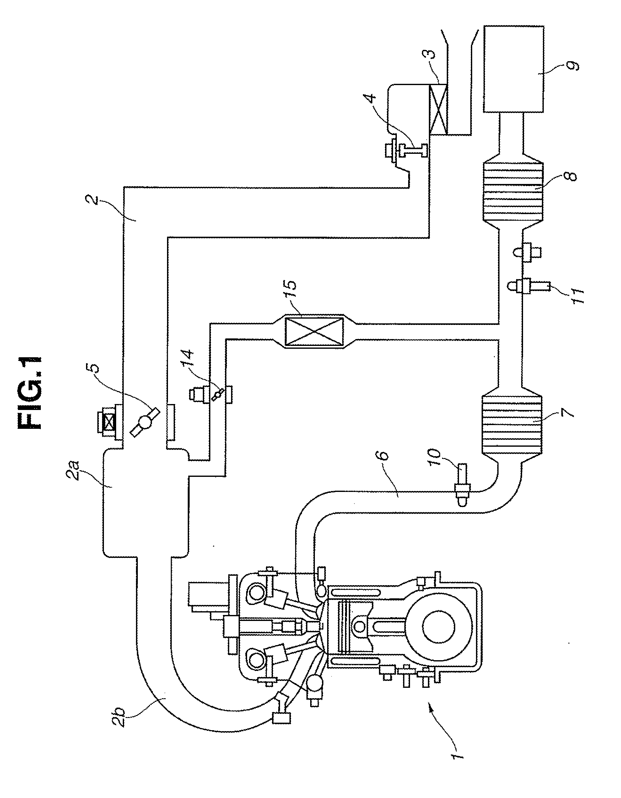
[0038]FIG. 1 is a schematic view of an internal combustion engine 1 to which an ignition control system according to one exemplary embodiment of the present invention is applied. In an intake passage 2 of the internal combustion engine 1, an air cleaner 3, an air flow meter 4 and a throttle valve 5 are disposed in order of mention from the upstream side. In an exhaust passage 6 of the internal combustion engine 1, an upstream-side catalytic converter 7, a downstream-side catalytic converter 8 and a muffler 9 are disposed in order of mention from the upstream side. An upstream-side air-fuel ratio sensor 10 and a downstream-side air-fuel ratio sensor 11 are arranged on upstream and downstream sides of the upstream-side catalytic converter 7, respectively. An exhaust gas recirculation passage 13 is branched off from a part of the exhaust passage 6 betwee...


PUM


Abstract

An ignition device for an internal combustion engine (1) includes a superpose voltage generation circuit (47) that, after the initiation of a discharge with the application of a discharge voltage by a secondary coil, applies a superpose voltage between electrodes of an ignition plug (29) in the same direction as the discharge voltage to continue a discharge current, and performs a superposed discharge in a superposed discharge activation range of high exhaust recirculation rate. Upon shift from the superposed discharge activation range of high exhaust recirculation rate to a superposed discharge deactivation range of low exhaust recirculation rate, the deactivation of the superposed discharge is delayed by a delay time ΔT. Although the exhaust gas recirculation rate becomes temporarily increased with decrease in intake air after the closing of an exhaust gas recirculation control valve, the superposed discharge is continued for the delay time ΔT so as to avoid misfiring.

Description

FIELD OF THE INVENTION[0001]The present invention relates to a technique for ignition of an internal combustion engine using an ignition coil assembly with primary and secondary coils and, more particularly, to an ignition control system and method for performing a superposed discharge with the application of a superpose voltage so as to compensate for a combustion deterioration of the internal combustion engine caused due to exhaust gas recirculation.BACKGROUND ART[0002]An ignition device is provided, including an ignition coil assembly with primary and secondary coils and an ignition plug connected to the secondary coil so as to, after the supply of a primary current to the primary coil, develop a high discharge voltage across the secondary coil by interruption of the primary current at a given ignition timing and thereby generate a discharge between electrodes of the ignition plug. The discharge voltage developed across the secondary coil and the magnitude of the discharge energy...

Claims


Application Information

Patent Timeline
Patent Type & Authority Applications(United States)
IPC IPC(8): F02P5/15F02D41/00F02M26/22F02P9/00
CPCF02P5/1504F02P9/002F02P9/007F02M26/22F02D41/0065F02B2075/125F02D2021/083F02D2041/389Y02T10/40
Inventor SHIRAISHI, TAISUKEYAGUCHI, TATSUYAMAEDA, HIROFUMI
Owner NISSAN MOTOR CO LTD
Why Eureka
Try Eureka