
Curved display panel, curved display panel device and method for fabricating the same

a technology curved display panel, which is applied in the field of display technology, can solve the problems of complex fabrication process, dark-state light leakage, and difficult to meet the needs of curved display panel, and achieve the effect of reducing the complexity of the fabricating process, reducing the stress, and reducing the risk of light leakag

Active Publication Date: 2016-11-03
BOE TECH GRP CO LTD +1
View PDF4 Cites 2 Cited by
  • Summary
  • Abstract
  • Description
  • Claims
  • Application Information

AI Technical Summary

Benefits of technology

The patent is about a new method for making curved display panels that have a natural bending degree, which reduces stress and prevents light leakage. The curved surface of the panel changes slowly, which makes it easier to control and simplifies the manufacturing process. Overall, this technique improves the quality and production efficiency of curved display panels.

Problems solved by technology

The curved display panel faces challenges, like complex fabricating process and dark-state light leakage (L0 light leakage).
In IPS (In-Plane Switching) and ADS (Advanced Super Dimension Switching) technology, light leakage in the dark-state is relatively serious due to the effect of their own modes.
However, OLED has the drawbacks of extremely high fabricating cost, immature technology, and low yield.
As a result, the curved display panel is subject to relatively larger stress and the curvature radius of each point on the curved surface changes rapidly, so that serious light leakage appears at a peripheral region of the curved display panel.
Additionally, due to the shape of the curved surface of the curved display panel, the fabricating process is complex.

Method used


Image

  • Curved display panel, curved display panel device and method for fabricating the same
  • Curved display panel, curved display panel device and method for fabricating the same
  • Curved display panel, curved display panel device and method for fabricating the same

Examples


first embodiment

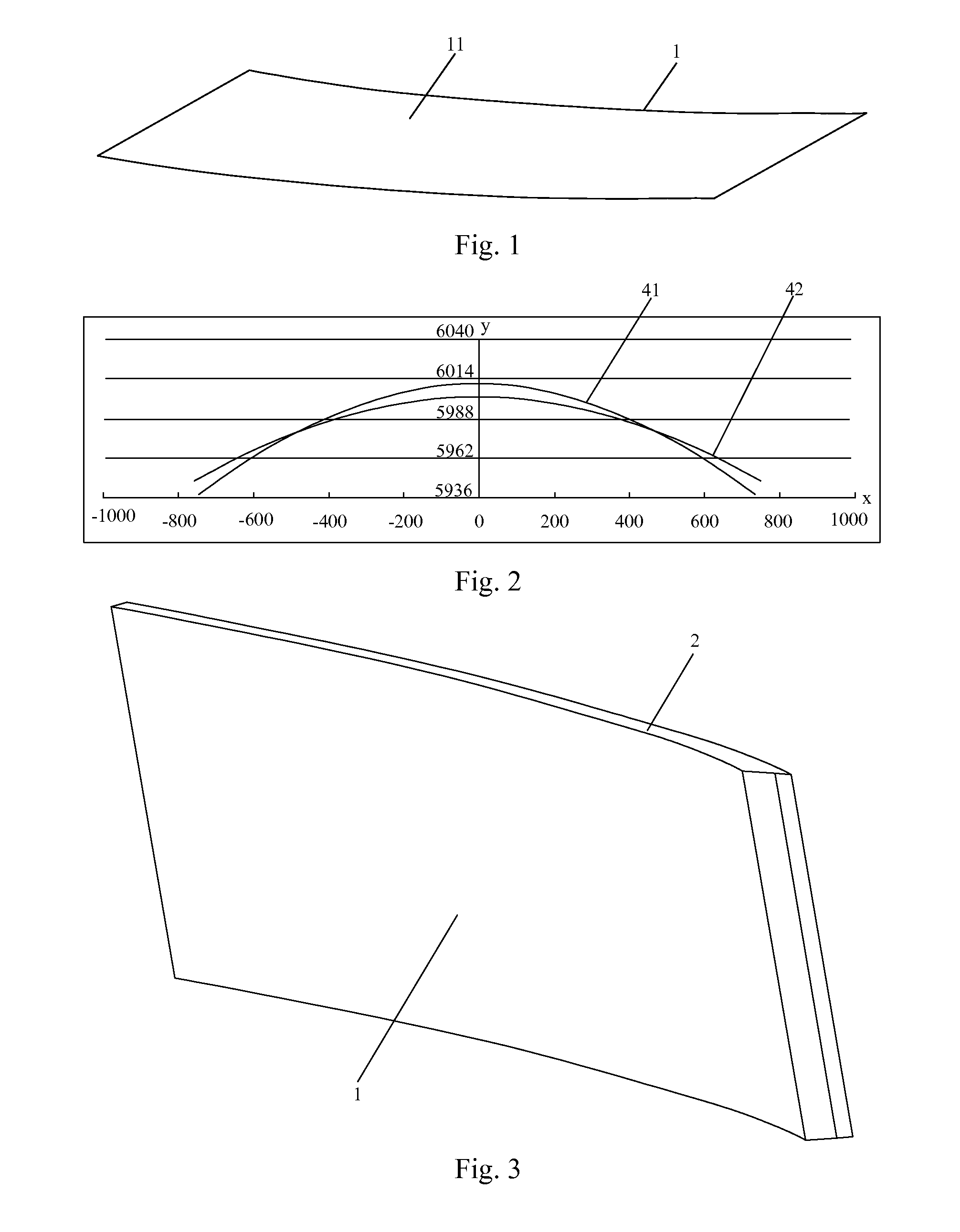
[0028]FIG. 1 is a structural view for a curved display panel in the present disclosure. As shown in FIG. 1, the curved display panel 1 has a light output face and a light input face, both of which are continuously curved surfaces 11.

[0029]In the present embodiment, the curved surfaces 11 have a bending shape of an elliptic curve. It is understood that “the curved surfaces 11 have a bending shape of an elliptic curve” in this context refers to a case in which, for example, when the curved surfaces 11 are arranged horizontally (as shown in FIG. 1), an intersecting line between the curved surfaces and a vertical plane which is parallel with the page is an elliptic curve. Additionally, when the elliptic curve is turned upside down, it is shown by an elliptic curve 41 in FIG. 2.

[0030]A curvature radius of the elliptic curve can be set according to requirements of the product. In the present embodiment, the curvature radius of the elliptic curve can preferably be 4200 mm-6600 mm.

[0031]In ...

second embodiment

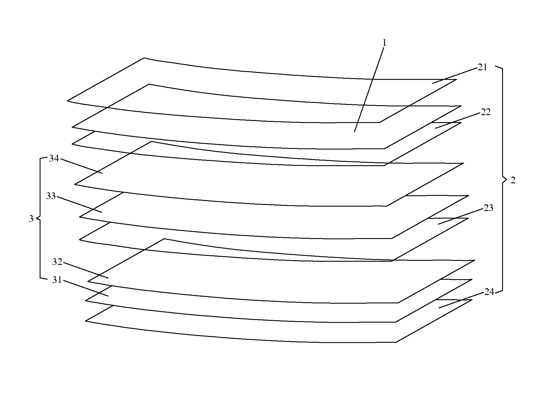
[0034]FIG. 3 is a structural view for a curved display device in the present disclosure, and FIG. 4 is an assembled view of the curved display device shown in FIG. 3. As shown in FIG. 3 and FIG. 4, the curved display device comprises an assembling frame 2 and the curved display panel 1 which is arranged in the assembling frame 2.

[0035]As shown in the figures, in the present embodiment, the assembling frame 2 comprises a bezel 21, a mold frame 22, a side mold frame 23, and a back cover 24. The curved display panel 1 can be mounted between the bezel 21 and the mold frame 22, and the back cover 24 acts as a back cover for the whole curved display device. The bezel 21, the mold frame 22, the side mold frame 23, and the back cover 24 have a light output face and a light input face, both of which are continuously curved surfaces and have a bending shape of an elliptic curve. The curved surfaces of the bezel 21, the mold frame 22, the side mold frame 23, and the back cover 24 can have a be...

third embodiment

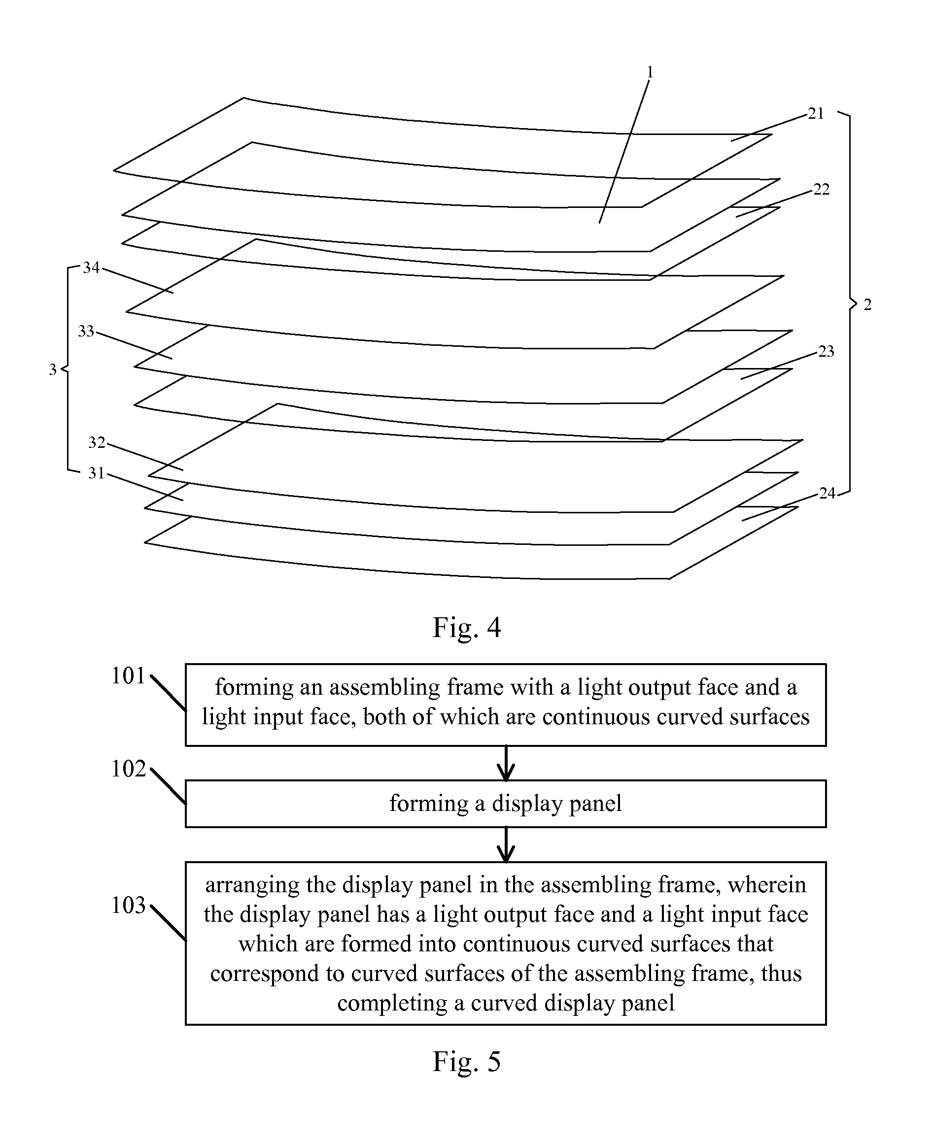
[0041]FIG. 5 is a flow chart of a method for fabricating a curved display device in the present disclosure. As shown in FIG. 5, the curved display device comprises an assembling frame and a curved display panel. The method comprises the following steps.

[0042]At step 101, an assembling frame is formed, both a light output face and a light input face of which are continuously curved surfaces.

[0043]In the present embodiment, the assembling frame comprises a bezel, a mold frame, a side mold frame, and a back cover. The bezel, the mold frame, the side mold frame, and the back cover have a light output face and a light input face, both of which are continuously curved surfaces. Step 101 can particularly comprise forming the bezel, the mold frame, the side mold frame, and the back cover respectively, wherein the bezel, the mold frame, the side mold frame, and the back cover have a light output face and a light input face, both of which are continuously curved surfaces.

[0044]In the present ...


PUM


Abstract

A curved display panel, a curved display device, and a method for fabricating the same are disclosed. Both the light output face and the light input face of the curved display panel are continuously curved surfaces. The curved display panel with a continuously curved surface has a bending degree which is closer to the natural bending degree of a liquid crystal panel, so that a relatively small stress is generated on the curved display panel, and the problem of serious peripheral light leakage caused by deformation of the curved display panel is alleviated. Besides, since the curvature radius of each point on the continuously curved surface changes slowly, the problem of serious peripheral light leakage caused by deformation of the curved display panel is alleviated, the complexity of the fabricating process is reduced, the fabricating process is simplified, and the production of the product is improved.

Description

RELATED APPLICATIONS[0001]The present application is the U.S. national phase entry of PCT / CN2015 / 076881, with an international filing date of Apr. 17, 2015, which claims the benefit of Chinese Patent Application No. 201410610592.9 filed Nov. 3, 2014, the entire disclosures of which are incorporated herein by reference.FIELD OF THE INVENTION[0002]The present disclosure relates to the field of display technology, and particularly to a curved display panel, a curved display device and a method for fabricating the same.BACKGROUND OF THE INVENTION[0003]The existing curved display panel like a curved surface TV has been applied widely. The curved display panel faces challenges, like complex fabricating process and dark-state light leakage (L0 light leakage). In IPS (In-Plane Switching) and ADS (Advanced Super Dimension Switching) technology, light leakage in the dark-state is relatively serious due to the effect of their own modes. Thus, OLED (Organic Light-Emitting Diode) mode or VA (Ver...

Claims


Application Information

Patent Timeline
IPC IPC(8): G02F1/1333H05K7/14G09F9/30
CPCG02F1/133308G09F9/301G02F2201/56G02F2001/133314G02F2001/133325H05K7/1417G09F9/30G02F1/133314G02F1/133325
Inventor SHAO, XIBINQU, YINGYINGZHANG, HONGLINZHAO, HEBINLEE, SEUNGMINWANG, DANLI, XIANG
Owner BOE TECH GRP CO LTD
Learn More