
System and method for reducing speed ripple of drive motor of electric vehicle

Inactive Publication Date: 2016-10-20
HYUNDAI MOTOR CO LTD
View PDF5 Cites 6 Cited by
  • Summary
  • Abstract
  • Description
  • Claims
  • Application Information

AI Technical Summary

Benefits of technology

The present invention provides a method for reducing speed ripple and torque ripple in an electric vehicle by monitoring inverter switching and generating a fixed or variable square wave to synchronize the excitation input signal. The peaks of the excitation input signal are adjusted to prevent them from coinciding with the inverter switching frequency, and the resolver excitation input signal may be fixed or variable based on the inverter switching frequency. This reduces noise and improves efficiency of the drive motor, reducing costs for NVH (noise, vibration, and harshness) generation and after-sales-service.

Problems solved by technology

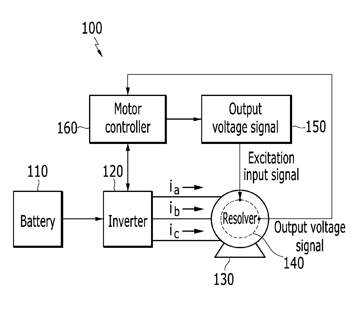
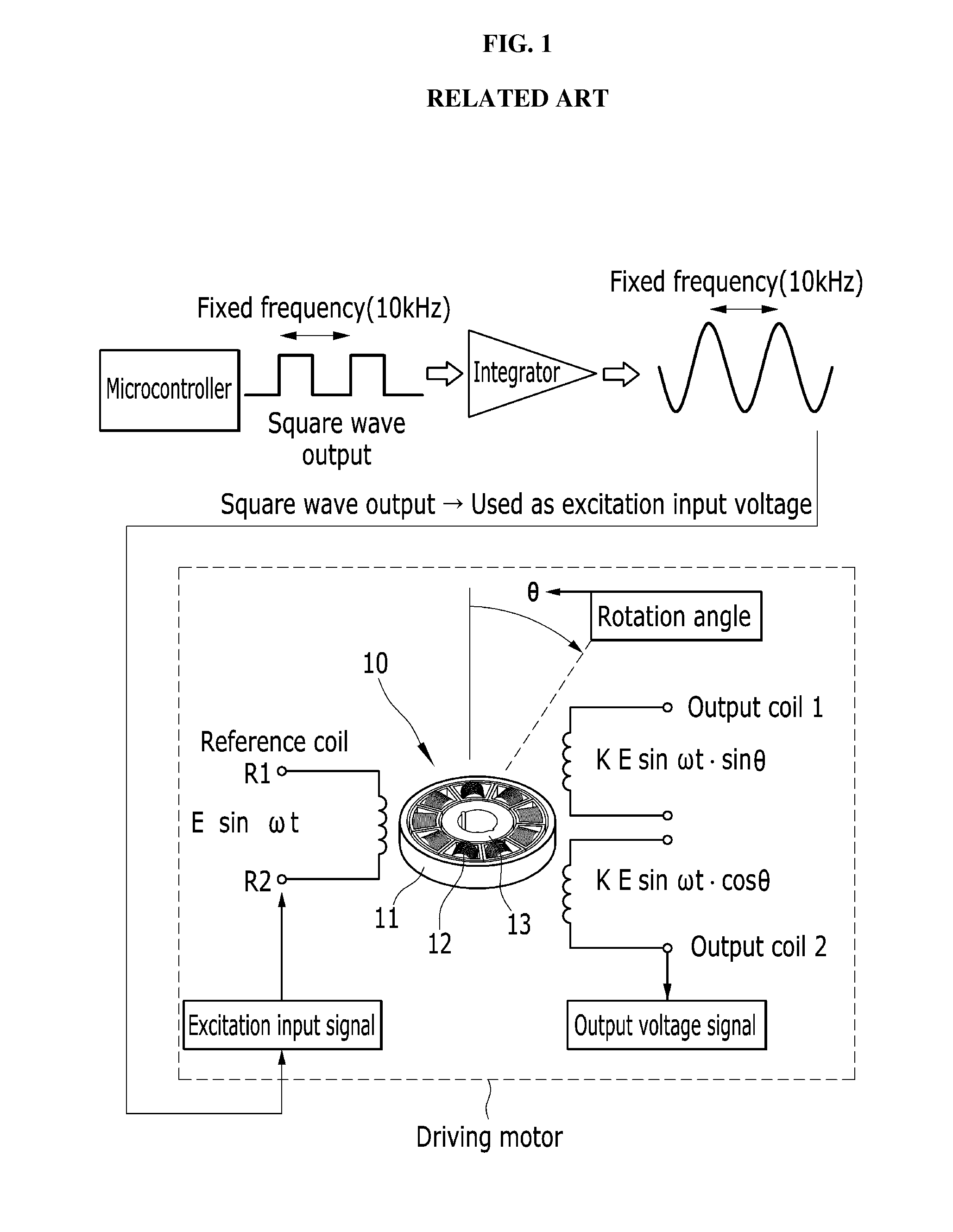
However, when the microcontroller switches an inverter on to convert direct current (e.g., DC) power supplied from a battery (e.g., not shown) to three-phase alternating current (e.g., AC) power and supplies the power to the drive motor, noise is generated in the excitation input signal and output voltage signal of the resolver.
For example, the switches in the inverter and the resolver circuit are proximate to each other, which causes switching noise to impact the resolver circuit.
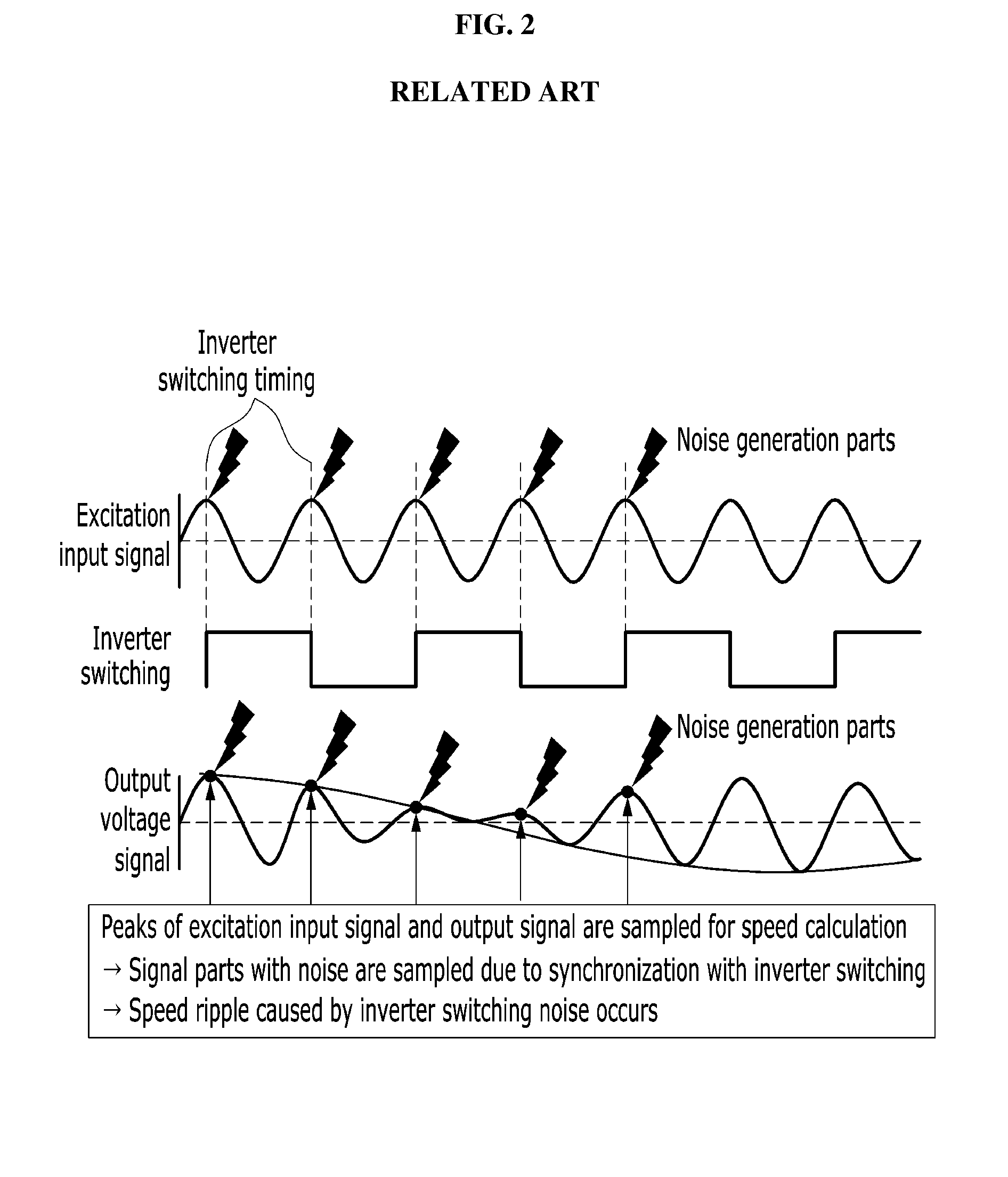
As shown in FIG. 2, the peaks of the excitation input signal of the resolver 10 and the inverter switching frequency are synchronized, and noise is generated in the excitation input signal and the output voltage signal, thereby causing excessive speed ripple.
Excessive speed ripple may lead to deterioration of noise vibration harshness (NVH), reduced gas mileage due to a reduction in drive motor efficiency caused by the instability of current control, and deterioration of durability caused by vehicle vibrations, resulting in frequent replacement of components and an increase in after-sales-service costs.

Method used


Image

  • System and method for reducing speed ripple of drive motor of electric vehicle
  • System and method for reducing speed ripple of drive motor of electric vehicle
  • System and method for reducing speed ripple of drive motor of electric vehicle

Examples


Embodiment Construction

[0027]In the following detailed description, only certain exemplary embodiments of the present invention have been shown and described, simply by way of illustration. As those skilled in the art would realize, the described exemplary embodiments may be modified in various different ways, all without departing from the spirit or scope of the present invention. Accordingly, the drawings and description are to be regarded as illustrative in nature and not restrictive. Like reference numerals designate like elements throughout the specification.

[0028]The terminology used herein is for the purpose of describing particular embodiments only and is not intended to be limiting of the invention. As used herein, the singular forms “a”, “an” and “the” are intended to include the plural forms as well, unless the context clearly indicates otherwise. It will be further understood that the terms “comprises” and / or “comprising,” when used in this specification, specify the presence of stated feature...


PUM


Abstract

A system and method for reducing drive motor speed ripple of an electric vehicle are provided. The system includes an inverter that converts DC power supplied from a battery to AC power and supplies the AC power to the drive motor by inverter switching. A resolver is configured to detect a speed of the drive motor and a position of a rotor, a signal generator includes a microcontroller that is configured to generate a square wave signal. An integrator is configured to convert the square wave to a sine wave, and apply a sine-wave excitation input signal to the resolver. Furthermore, a motor controller is configured to adjust the frequency of the excitation input signal to prevent the inverter switching frequency of the inverter and the peaks of an output voltage signal sampled for speed calculation from overlapping.

Description

CROSS-REFERENCE TO RELATED APPLICATION[0001]This application claims priority to and the benefit of Korean Patent Application No. 10-2015-0054024 filed in the Korean Intellectual Property Office on Apr. 16, 2015, the entire contents of which are incorporated herein by reference.BACKGROUND[0002](a) Field of the Invention[0003]The present invention relates to a system and method for reducing drive motor speed ripple of an electric vehicle and more particularly to prevent the peaks of an excitation voltage signal input into a resolver from overlapping an inverter switching timing, to reduce drive motor speed ripple of an electric vehicle.[0004](b) Description of the Related Art[0005]Recently, there has been an increasing need for eco-friendly vehicles to comply with the demand for higher gas mileage in vehicles and strict exhaust gas regulations in global markets. Potential resolutions for this situation include the development of hybrid electric vehicles (HEV), plug-in hybrid electric ...

Claims


Application Information

Patent Timeline
IPC IPC(8): H02P6/08H02P6/16B60L11/18H02P27/06
CPCH02P6/08B60L11/1803H02P6/165H02P27/06H02P6/16B60L50/51Y02T10/72Y02T10/70
Inventor LIM, JAE SANGRHO, JEONGWONKANG, GU BAEKIM, YOUNG UN
Owner HYUNDAI MOTOR CO LTD
Learn More