Organic el display device
a display device and electroluminescent technology, applied in the direction of organic semiconductor devices, semiconductor devices, diodes, etc., can solve the problems of increasing the pixel pitch, affecting the quality of the image, and the contact hole 32/b>, so as to reduce the shading effect, the effect of high opening ratio of the pixel
- Summary
- Abstract
- Description
- Claims
- Application Information
AI Technical Summary
Benefits of technology
Problems solved by technology
Method used
Image
Examples
first embodiment
[0030]An organic EL display device is an active matrix display device, and is incorporated into a television, a personal computer, a mobile terminal, and a cellular phone as a display panel. FIG. 1 is a schematic view illustrating a general configuration of an organic EL display device 60 according to a first embodiment of the present invention. The organic EL display device 60 includes a pixel array portion 62 which is a display area for displaying an image, and a drive portion that drives the pixel array portion 62.
[0031]In the pixel array portion 62, OLEDs 64 and pixel circuits 66 are arranged in a matrix in correspondence with pixels (or sub-pixels). Each of the pixel circuits 66 includes plural thin film transistors (TFT) 68, 70, and a capacitor 72. An anode electrode of each OLED 64 is connected to the drive TFT 70. Also, cathode electrodes of all the OLEDs 64 are configured by a common electrode as will be described later.
[0032]On the other hand, the drive portion includes a ...
second embodiment
[0064]A description will be given of the organic EL display device 60 according to a second embodiment of the present invention below. In this embodiment, the components common to those in the first embodiment are denoted by identical symbols, and a description of those components will be basically omitted, and differences from the first embodiment will be mainly described.
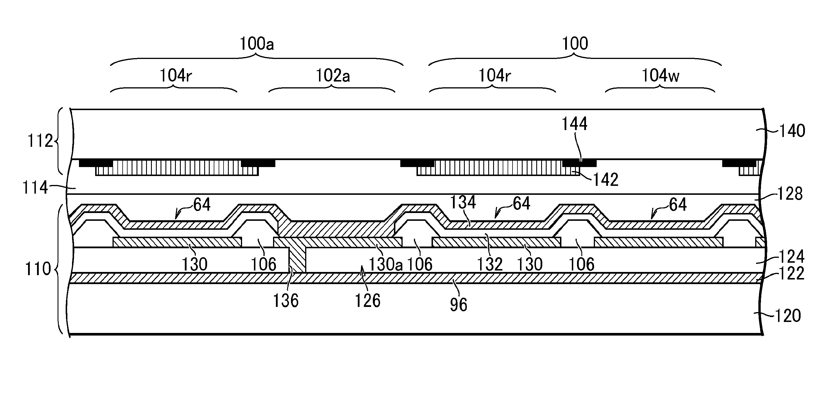
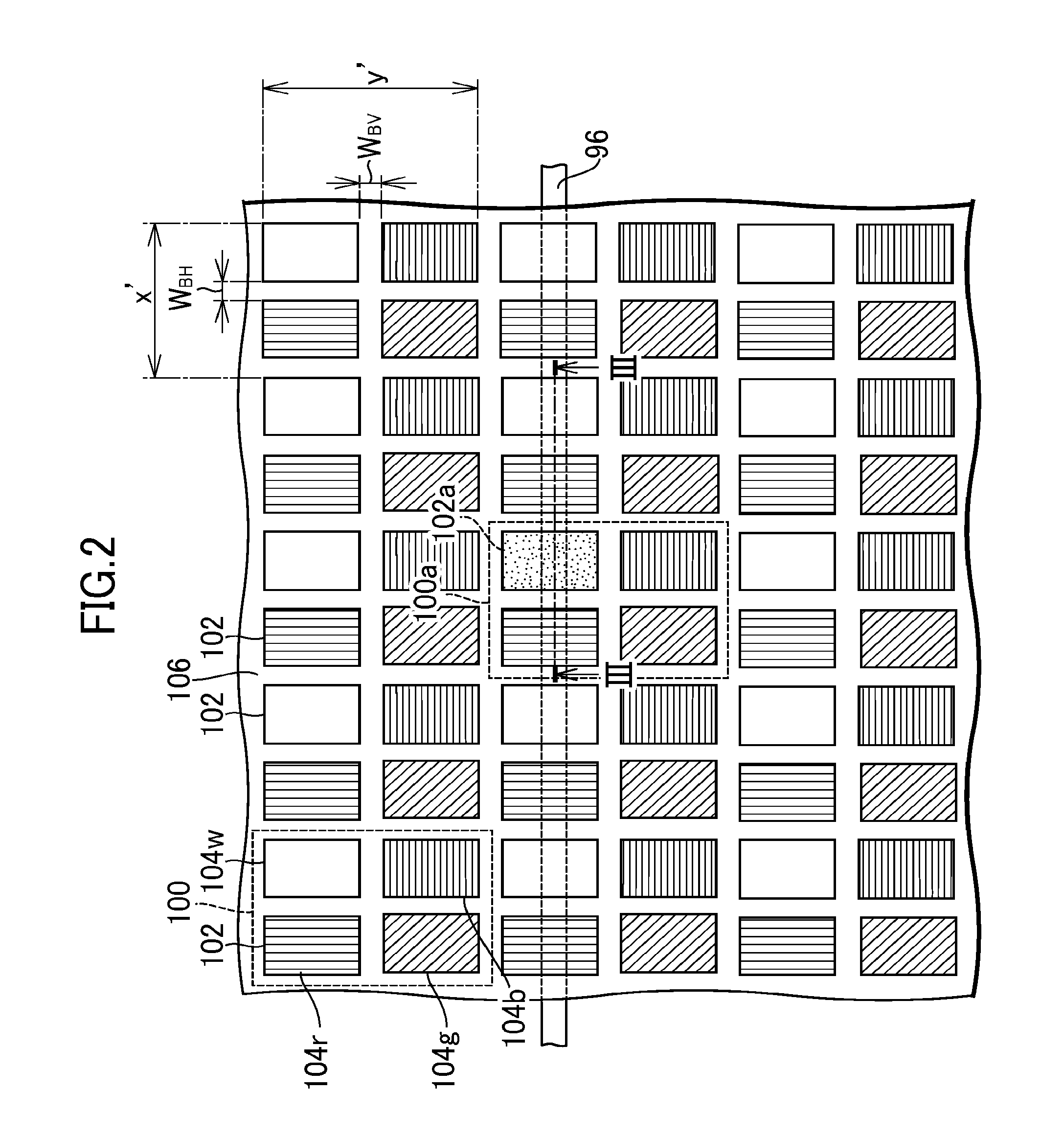
[0065]Each of the pixels 100 according the second embodiment includes four sub-pixels of RGBW which are Bayer-arrayed as in the first embodiment. Differences between the second embodiment and the first embodiment reside in the structure of the irregular pixel. FIG. 5 is a schematic plan view of an irregular pixel 100b according to the second embodiment. In the irregular pixel 100h, the cathode contact 126 is formed in a part of an area 160 corresponding to an opening area of the W sub-pixel 104w of each basic pixel 100 instead of the structure of the organic light emitting element. Specifically, the area 160 is pa...
third embodiment
[0067]A description will be given of the organic EL display device 60 according a third embodiment of the present invention. In this embodiment, the components common to those in the first embodiment are denoted by identical symbols, and a description of those components will be basically omitted, and differences from the first embodiment will be mainly described.
[0068]FIG. 6 is a schematic partial plan view of a pixel array portion 62 in an organic EL display device 60 according to this embodiment. This embodiment is different from the first embodiment in that a basic pixel 200 includes three sub-pixels of RGB, and the cathode contact 126 is formed in an opening area 102b located at a position in an irregular pixel 200a corresponding to the B sub-pixel in the basic pixel 200.
[0069]In this embodiment, the irregular pixel 200a includes two sub-pixels of RG. For that reason, a deficit of the B sub-pixel caused by the provision of the cathode contact 126 cannot be compensated by signal...
PUM
| Property | Measurement | Unit |
|---|---|---|
| display area | aaaaa | aaaaa |
| cross-section | aaaaa | aaaaa |
| voltage | aaaaa | aaaaa |
Abstract
Description
Claims
Application Information
 - R&D
- Intellectual Property
- Life Sciences
- Materials
- Tech Scout
- Unparalleled Data Quality
- Higher Quality Content
- 60% Fewer Hallucinations
Browse by: Latest US Patents, China's latest patents, Technical Efficacy Thesaurus, Application Domain, Technology Topic, Popular Technical Reports.
© 2025 PatSnap. All rights reserved.Legal|Privacy policy|Modern Slavery Act Transparency Statement|Sitemap|About US| Contact US: help@patsnap.com


