
Steering column device

a technology of steering column and clamping device, which is applied in the direction of steering parts, vehicle components, transportation and packaging, etc., can solve the problems that the bending rigidity of the steering column device could be deteriorated in the vertical and lateral directions of the whole device, and achieve the effect of reducing the bending rigidity of the clamping parts and eliminating the dispersion of operating for

Active Publication Date: 2016-10-06
FUJI KIKO CO LTD
View PDF0 Cites 2 Cited by
  • Summary
  • Abstract
  • Description
  • Claims
  • Application Information

AI Technical Summary

Benefits of technology

This patent describes a steering column device that improves bending rigidity in both vertical and lateral directions. The device includes a lower jacket and an upper jacket that are fastened together using co-fastening pins. This provides stability and reduces bending rigidity issues. The device also has a characteristic frequency that helps reduce vibrations. Additionally, the device includes slide contact pieces that are designed to prevent shaking or rattling. Overall, this patent provides a solution for improving the stability and durability of steering column devices.

Problems solved by technology

In this structure, however, as the outer column and the inner column are strongly fixed in only a slit's portion where the fastening member is arranged, there is a risk that the steering column device could become deteriorated in bending rigidity in the vertical and lateral directions of the whole device.

Method used


Image

  • Steering column device
  • Steering column device
  • Steering column device

Examples


Embodiment Construction

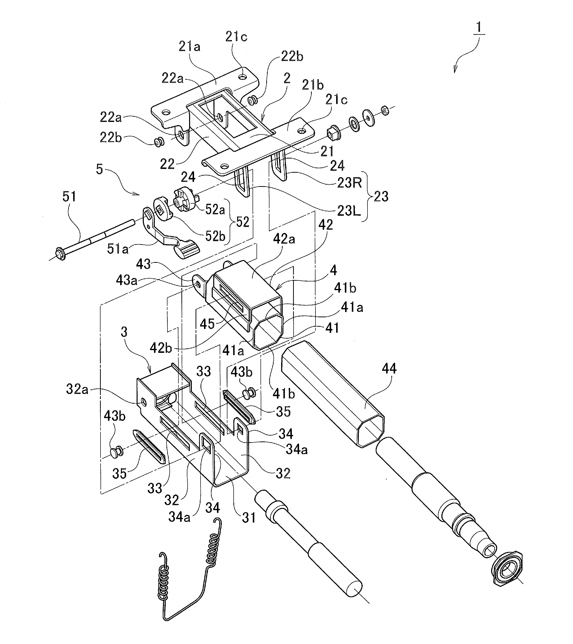
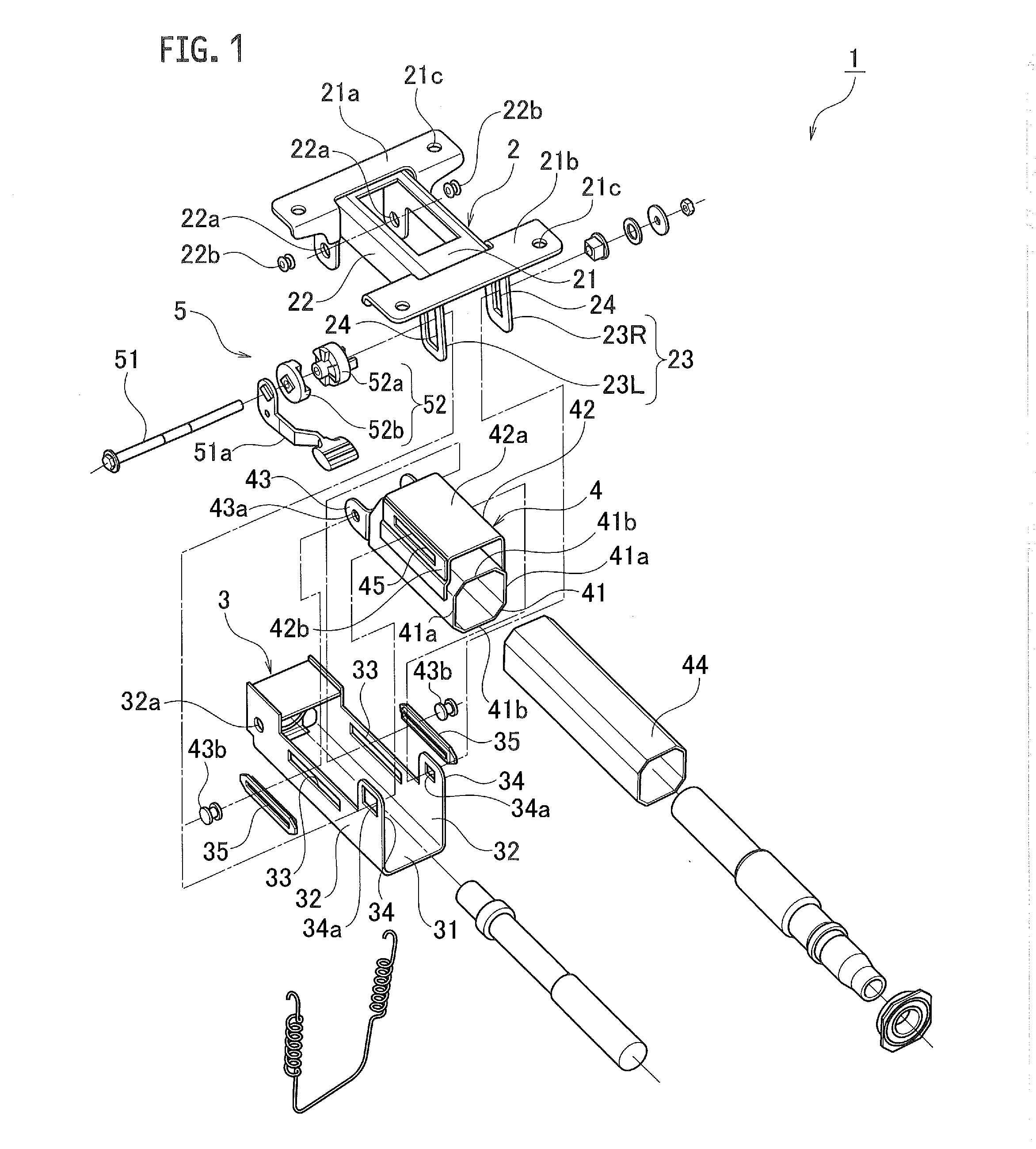
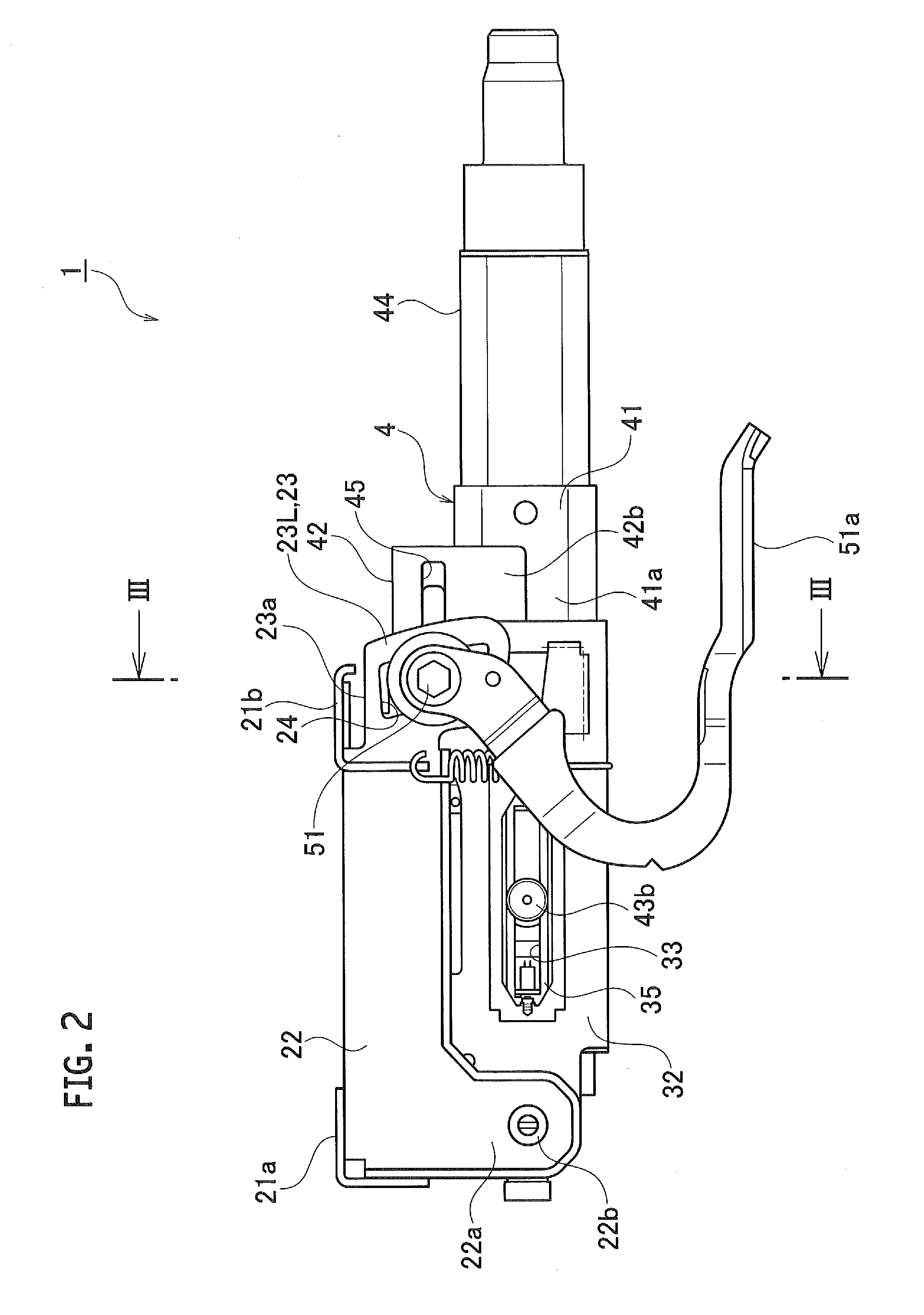
[0019]An embodiment will be described with reference to the drawings. As illustrated in FIGS. 1 to 3, a steering column device 1 according to the embodiment is a manual type steering column device. The steering column device 1 according to the embodiment includes an attachment bracket 2 for fixing the column device 1 to a vehicle body, a lower jacket 3 which is supported to the attachment bracket 2 so as to be swingable (capable of adjusting its tilt position) in a vehicle vertical direction, an upper jacket 4 which is supported to the lower jacket 3 so as to be movable (capable of adjusting its telescopic position) in a vehicle longitudinal direction, and a lock mechanism 5 which fastens the attachment bracket 2, the lower jacket 3, and the upper jacket 4 integrally.

[0020]The attachment bracket 2 includes a plate-shaped attachment body 21 arranged along a horizontal direction and a pair of hanging parts 22 hanging from left and right marginal parts of the attachment body 21, and is...


PUM


Abstract

A steering column device includes: telescopic guide holes provided in one of a pair of upstanding walls constituting a lower jacket and a pair of vertical walls constituting an upper jacket and also constituted by through-holes opening along a vehicle longitudinal direction; and co-fastening pins penetrating through the telescopic guide holes movably in the telescopic guide holes by which the upstanding walls and the vertical walls are jointly fastened to each other so that the vertical walls can move on the upstanding walls.

Description

CROSS REFERENCE TO RELATED APPLICATION[0001]The present application is based on, and claims priority from Japanese Patent Application No. 2015-070657, filed Mar. 31, 2015, the disclosure of which is hereby incorporated by reference herein in its entirety.TECHNICAL FIELD[0002]The present application relates to a steering column device capable of a tilt and telescopic operation.BACKGROUND ART[0003]As conventional examples of the steering column device capable of a tilt and telescopic operation, there are constitutions disclosed in Patent Document 1 (JP 2001-347953 A) and Patent Document 2 (EP 1910148 B1). Each of these steering column devices includes a tilt-position adjustment mechanism for performing positional adjustment of a steering wheel in a vehicle vertical direction and a telescopic-position adjustment mechanism for performing positional adjustment of the steering wheel in a vehicle longitudinal direction.[0004]The steering column device of Patent Document 1 includes an attac...

Claims


Application Information

Patent Timeline
Patent Type & Authority Applications(United States)
IPC IPC(8): B62D1/185B62D1/187B62D1/184
CPCB62D1/185B62D1/187B62D1/184
Inventor MATSUNO, MITSUYOSHIITO, TADAOSAWAMURA, KOJI
Owner FUJI KIKO CO LTD
Learn More