
Time-multiplexed spectrally controlled interferometry

a spectrally controlled, time-multiplexed technology, applied in the field of interferometry, can solve the problems of mechanical complexity, loss of light, and coherent noise as the main source of measurement errors

Active Publication Date: 2016-09-29
OLSZAK ARTUR
View PDF2 Cites 3 Cited by
  • Summary
  • Abstract
  • Description
  • Claims
  • Application Information

AI Technical Summary

Benefits of technology

The invention is a tunable light source that produces multiple wavelengths during sequential fractions of the integration time of an interferometer. This source is controlled to produce interference fringes that can be detected within the measurement space of the interferometric apparatus. The wavelengths are selected so as to produce a visible correlogram at each integration time according to SCI principles. The tunable light source can be used with conventional high-coherence interferometry or white-light interferometry. The invention combines the advantages of both approaches and provides a novel way to produce sequential frames of phase shifted correlograms with common-path apparatus. The technical effects of this invention include improved accuracy and sensitivity in interferometric analysis and improved performance of interferometers in various applications.

Problems solved by technology

Typically, coherent noise is one of the main sources of measurement errors in conventional interferometry.
Such arrangements can be complex and prevent the use of common-path interferometers, therefore forfeiting the above-described advantages.
These approaches suffer from loss of light and mechanical complexity, making them impractical.

Method used


Image

  • Time-multiplexed spectrally controlled interferometry
  • Time-multiplexed spectrally controlled interferometry
  • Time-multiplexed spectrally controlled interferometry

Examples


Embodiment Construction

[0019]As used in this disclosure, “white light” is intended to refer to any broadband light of the type used in the art of white-light interferometry, typically having a bandwidth in the order of many nanometers. “Monochromatic” light, on the other hand, is intended to refer to any high-coherence narrowband light capable of producing high-contrast interference fringes within the entire measurement space of the particular apparatus utilizing such light as a source. For the purposes of this disclosure, a source is defined as “temporally coherent” if, at any given time, interference fringes can be detected within the measurement space of the interferometric apparatus used to implement SCI. With reference to light in general, the terms “frequency” and “wavelength” are used alternatively, as commonly done in the art, because of their well known inverse relationship. “Optical path difference” or “OPD” and “time delay” are used alternatively because of their space / time relationship in inte...


PUM


Abstract

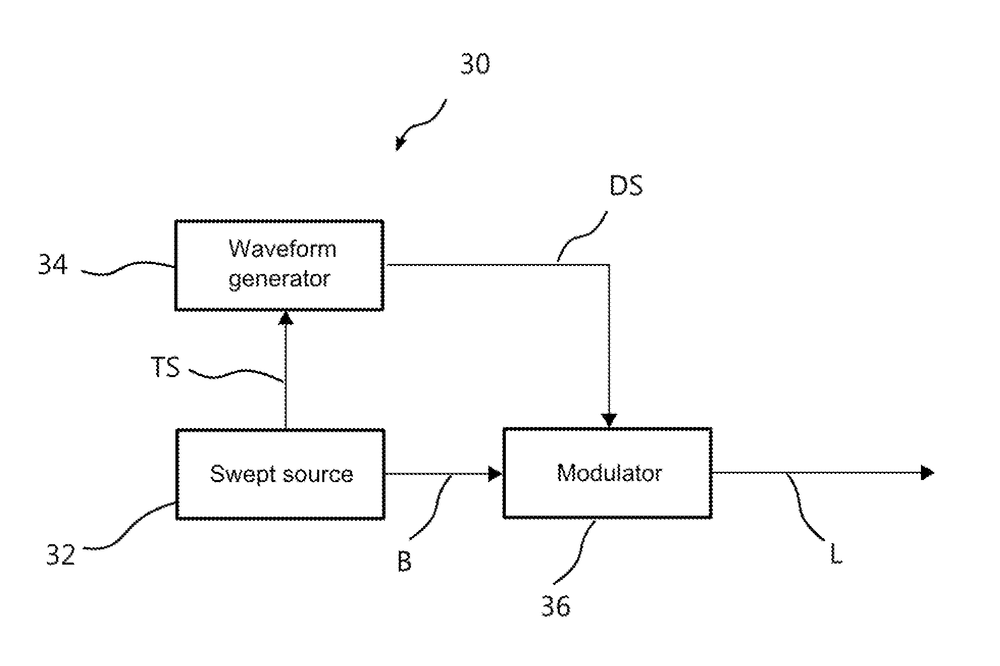
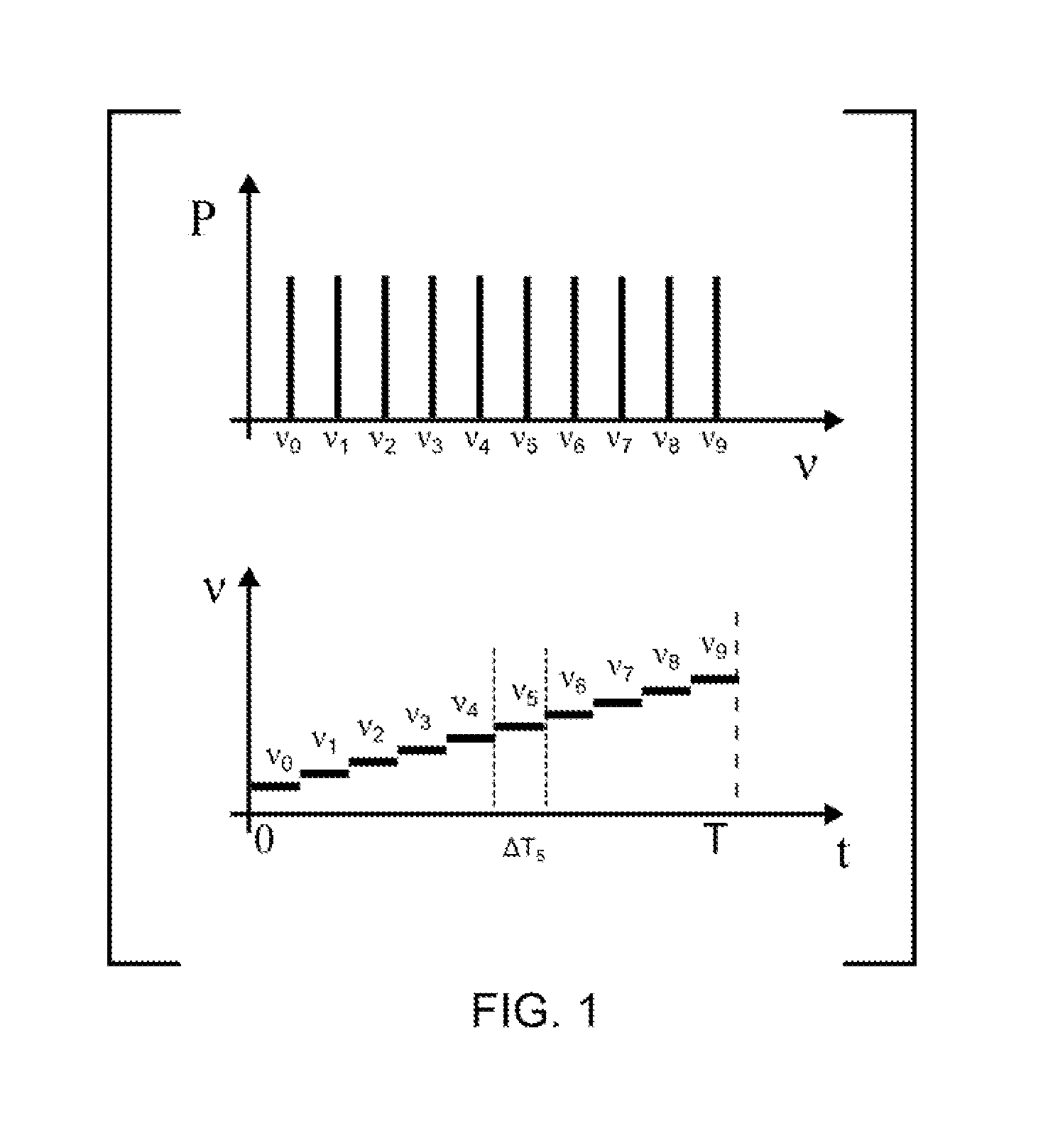
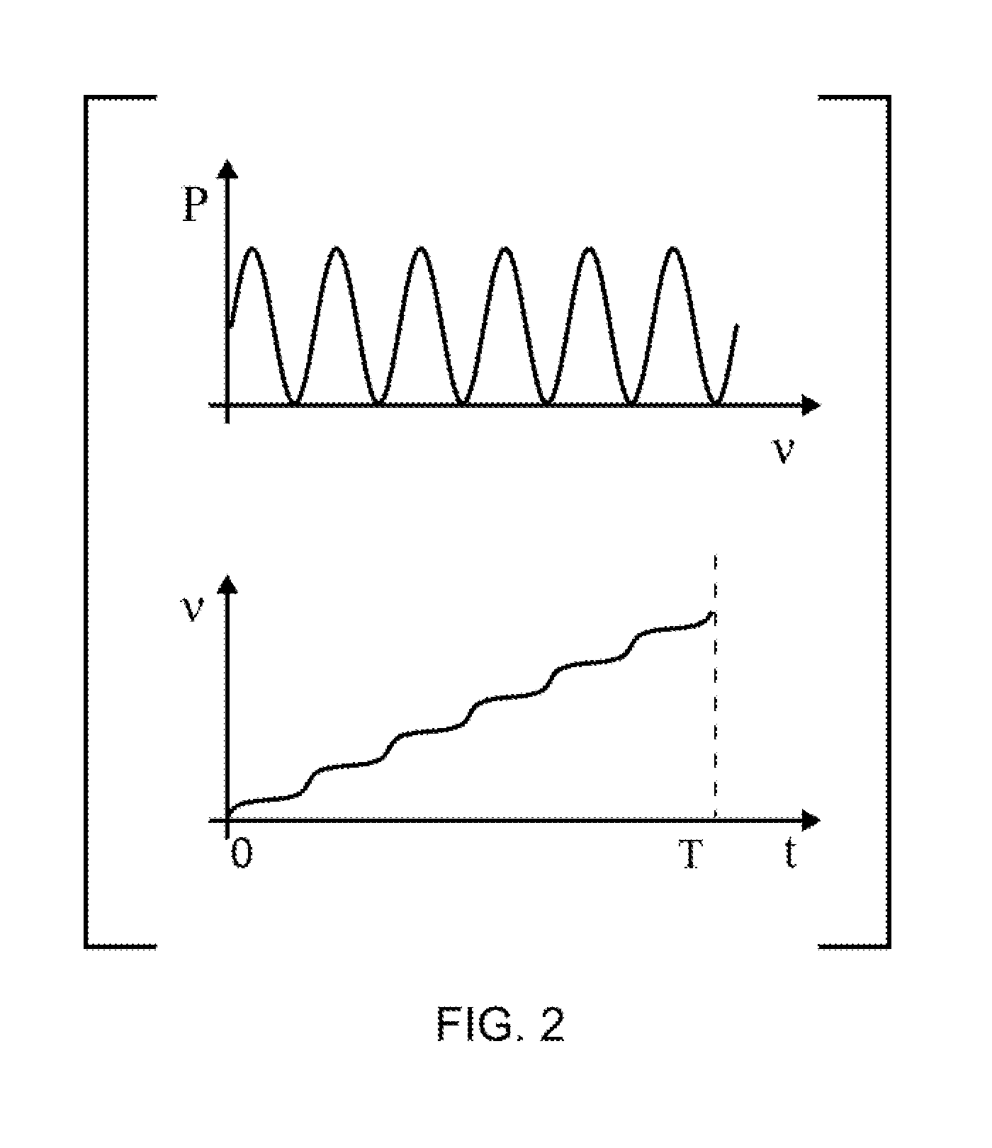
A tunable light source having a temporal coherence length such that interference fringes are detected within the optical path difference of the interferometer is spectrally controlled to produce multiple wavelengths during sequential fractions of the integration time of the detector of the interferometer. The wavelengths are selected so as to produce a visible correlogram at each integration time according to spectrally controlled interferometry (SCI) principles. Such different wavelengths may be produced by stepwise or continuous modulation. The modulation step is repeated sequentially while changing the period of modulation to produce a succession of predetermined spatial patterns of interference fringes, as required for interferometric measurements. The approach enables the practice of SCI with common-path apparatus used for conventional phase shifting, thereby combining the advantages of high-coherence and white-light interferometry. A suitable time-modulated source combines a coherent source with an optical modulator and a waveform generator synchronized with the source.

Description

RELATED APPLICATIONS[0001]This application is a Continuation-In-Part Application of U.S. Ser. No. 14 / 832,052, filed Aug. 21, 2015, which was based on and claimed the priority of U.S. Provisional Application No. 62 / 043,366, filed Aug. 28, 2014, both hereby incorporated by reference in their entirety.BACKGROUND OF THE INVENTION[0002]1. Field of the Invention[0003]This invention relates in general to the field of interferometry and, in particular, to a novel approach to providing a spectrally controlled source of interferometric light using time-averaged exposure.[0004]2. Description of the Prior Art[0005]Spectrally controlled interferometry (“SCI”) is a recently developed interferometric technique that allows implementation of white light interferometry (“WLI”) measurement schemes in common-path interferometers. See U.S. Pat. No. 8,422,026, No. 8,810,884 and No. 8,675,205, all hereby incorporated by reference. In contrast to conventional, high-coherence, laser interferometry, WLI is c...

Claims


Application Information

Patent Timeline
Patent Type & Authority Applications(United States)
IPC IPC(8): G01J9/02H01S3/00
CPCG01J9/02G01J2009/0249H01S3/0085G01B9/02004G02F1/0121G02F2203/05G01B9/02005
Inventor OLSZAK, ARTUR
Owner OLSZAK ARTUR
Learn More