Flapping abutment mechanism for a lift assembly, a rotorcraft rotor including the abutment mechanism, and a rotorcraft

Active Publication Date: 2016-09-29
EUROCOPTER
View PDF2 Cites 2 Cited by
  • Summary
  • Abstract
  • Description
  • Claims
  • Application Information

AI Technical Summary

Benefits of technology

The invention proposes a rotor with a simple mechanism to limit the movement of lifting parts on the main bladed rotor of a helicopter. This mechanism is straightforward to achieve and reduces the likelihood of flapping or bending during operation.

Problems solved by technology

The upward and downward travel of a lift assembly is thus limited by the authorized travel of the link.

Method used


Image

  • Flapping abutment mechanism for a lift assembly, a rotorcraft rotor including the abutment mechanism, and a rotorcraft
  • Flapping abutment mechanism for a lift assembly, a rotorcraft rotor including the abutment mechanism, and a rotorcraft
  • Flapping abutment mechanism for a lift assembly, a rotorcraft rotor including the abutment mechanism, and a rotorcraft

Examples


Embodiment Construction

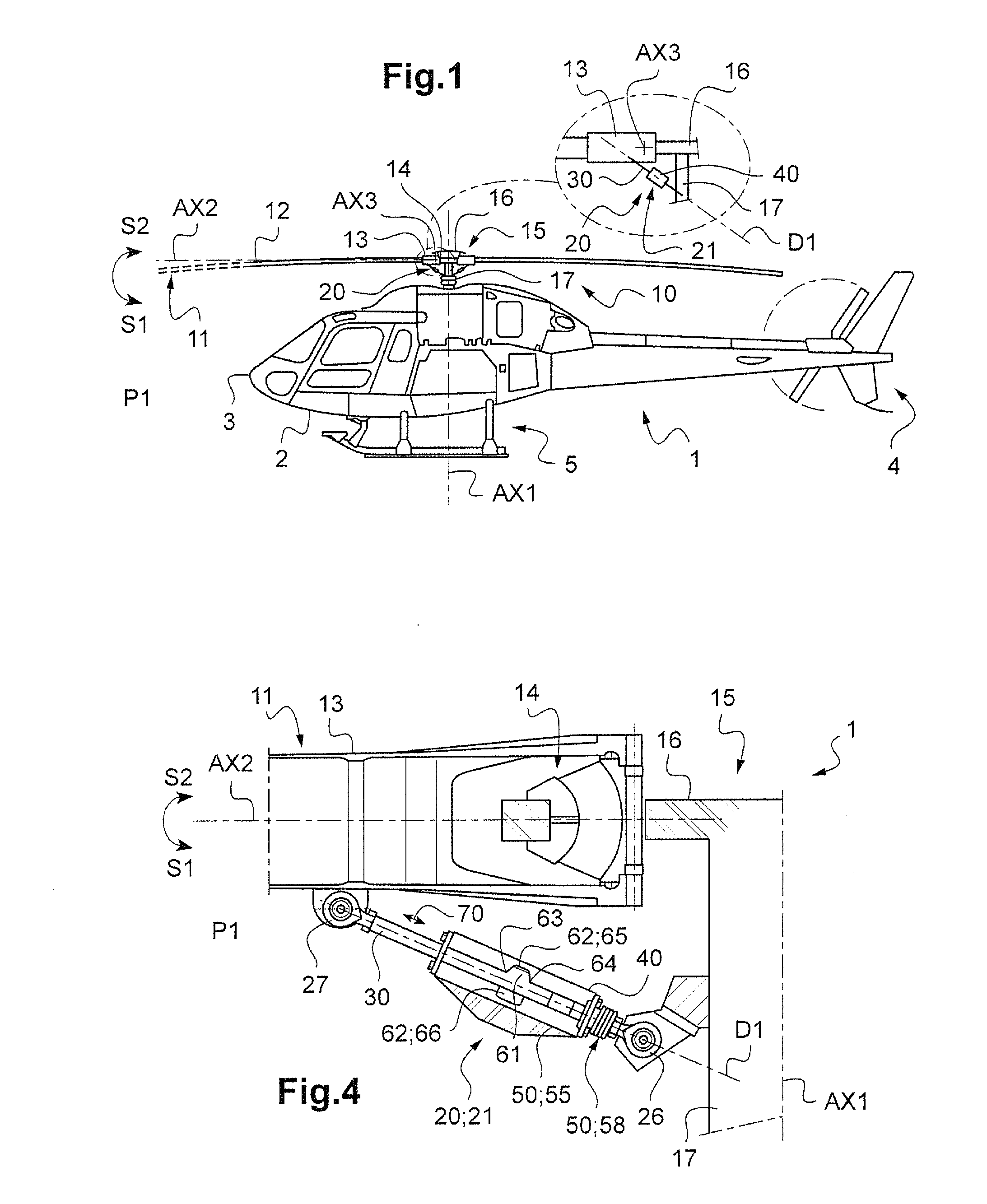
[0102]FIG. 1 shows an aircraft 1 of the invention.

[0103]The aircraft comprises an airframe 2 extending from a nose 3 to a tail end 4. The airframe stands on the ground via landing gear 5.

[0104]The airframe also carries at least lift and / or propulsion rotor 10. In FIG. 1, the aircraft 1 is thus a rotorcraft.

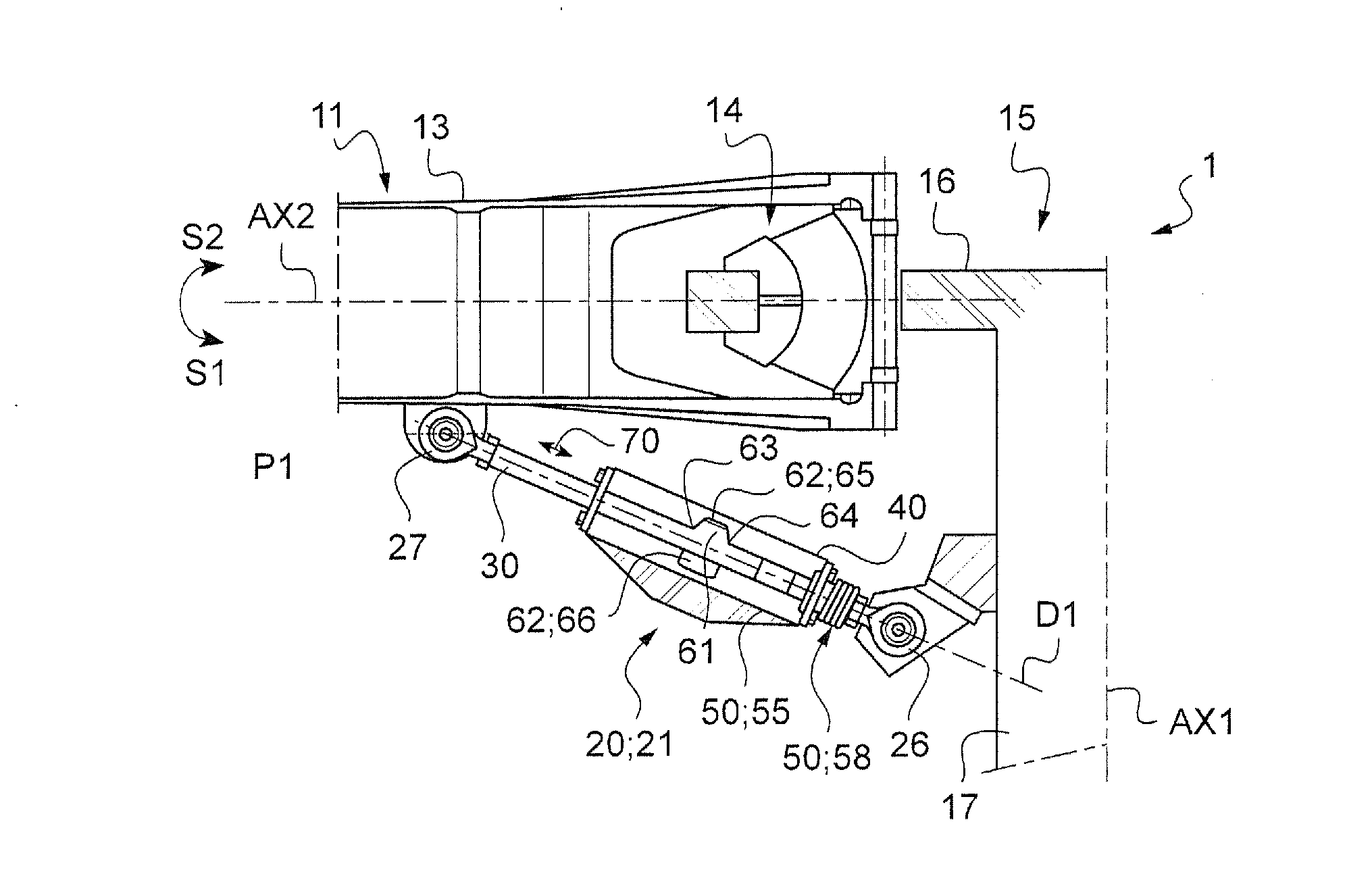
[0105]The rotor 10 has a plurality of lift assemblies 11, each carried by a driven system 15. The drive system 15 is connected to a power plant in order to drive the lift assemblies 11 in rotation around an axis in elevation AX1.

[0106]By way of example, the drive system 15 comprises a mast 17 secured to a hub 16. The hub 16 is thus not hinged to the mast 17 in FIG. 1. Furthermore, the drive system may include a scissors linkage connecting the mast to a set of swashplates for controlling the pitch of the blades.

[0107]Each lift assembly 11 includes a lift element 12 and a cuff 13 together forming a blade. The cuff may be incorporated in the lift element or it may be to the lift elem...


PUM


Abstract

An abutment mechanism for a lift assembly of an aircraft. The abutment mechanism comprises a single rigid link having variable travel, the link comprising a rod and a body, the rod being movable in translation relative to the body along the longitudinal direction through said travel, the abutment mechanism including a movement member for adjusting an amplitude of the travel as a function of at least one predetermined parameter, the link having two endpieces suitable for being hinged respectively to a said lift assembly and to a said drive system.

Description

CROSS REFERENCE TO RELATED APPLICATION[0001]This application claims priority to French patent application No. FR 15 00621 filed on Mar. 27, 2015, the disclosure of which is incorporated in its entirety by reference herein.BACKGROUND OF THE INVENTION[0002](1) Field of the Invention[0003]The present invention relates to a flapping abutment mechanism for a lift assembly, to a rotorcraft rotor, and to a rotorcraft having such a rotor.[0004]The invention thus lies in the technical field of rotorcraft rotors. More specifically, the invention lies in the field of abutments fitted to such rotors in order to limit flapping movement of the lift elements carried by the rotor.[0005](2) Description of Related Art[0006]A rotorcraft usually has at least one rotor for providing the rotorcraft with at least some of its lift and possibly also with propulsion.[0007]A rotor comprises at least two lift assemblies that are rotated by a drive system. Each lift assembly is fastened in particular to the dri...

Claims


Application Information

Patent Timeline
IPC IPC(8): B64C27/32B64C27/625
CPCB64C27/625B64C27/322F16F9/56F16F2230/16
Inventor MASSAL, FABIEN
Owner EUROCOPTER
Why Eureka
Try Eureka