
Internal joint bracing system and suture anchoring assembly therefore

Inactive Publication Date: 2016-09-29
ADVANCED BONE ANCHOR
View PDF3 Cites 4 Cited by
  • Summary
  • Abstract
  • Description
  • Claims
  • Application Information

AI Technical Summary

Benefits of technology

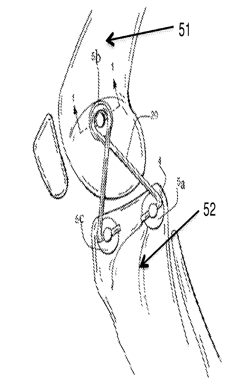
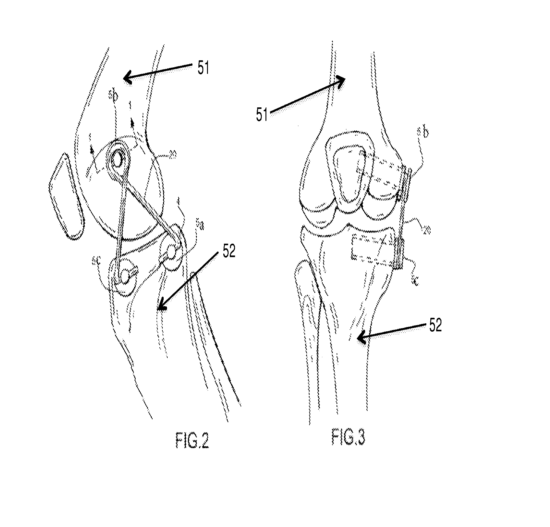
The present invention introduces a new method to control unstable joints through an extra-capsular approach. This method limits the damaging joint motions and internal slippage that cause high stresses commonly observed in people with joint dysfunction. The method uses artificial ligament anchors that allow for fixation across a joint from bone to bone, while permitting the tether to move through a range of positions without damaging the tether at the anchor interface. This method can prevent or slow progression of arthritic wear, pain, and instability of the joints in people with joint dysfunction. The invention provides a simpler and more effective technique for surgical tacking of ligament augments in place and allows a wide range of surgeons to use this technology. The invention also offers a unique construct that can utilize large radii bending, universal joints, and / or tensioners.

Problems solved by technology

Specifically, as seen in these populations, there can be severe combined ligament insufficiency and / or deficiencies leading to instability of the joint causing early progressive joint wear, arthritis, pain and dysfunction.
Existing externally worn joint braces have been used for years but have been uncomfortable and ineffective in providing the type of control and stability needed to control pathologic sequel of an unstable joint.
The other traditional option of intra-articular ligament replacements are complex to install, have high failure rates and are generally not effective over time.
Thus, there has been a general failure of external brace.

Method used


Image

  • Internal joint bracing system and suture anchoring assembly therefore
  • Internal joint bracing system and suture anchoring assembly therefore
  • Internal joint bracing system and suture anchoring assembly therefore

Examples


Embodiment Construction

[0037]The invention will now be more specifically described with reference to the aforementioned FIGS. 1-10.

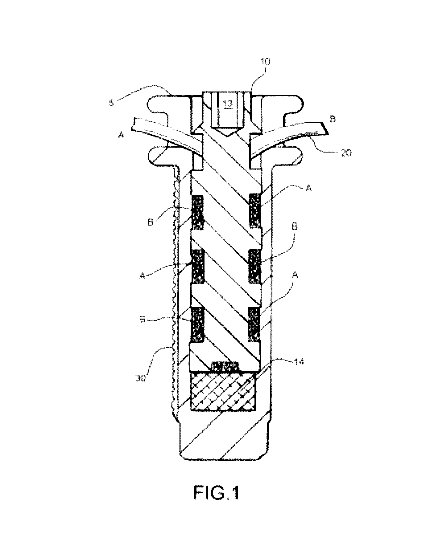
[0038]In accordance with an embodiment of the present invention a novel anchor assembly 1 is securely anchored to bone to attach a synthetic or biologic tether or suture 20. (Tether and suture are used interchangeably herein to refer to the material attached to the bone anchor assembly for forming an internal bracing system according to an embodiment of the present invention.) The anchor assembly 1 includes an anchor member 5 and a central set screw 10. The anchor member 5 and set screw 10 are made from biocompatible, high strength materials. Details of the anchor member 5 are illustrated in FIGS. 4-9. Details of the central set screw 10 are illustrated in FIG. 10. The tether 20 is connected to the anchor assembly 1 through interaction of the anchor member 5 and the set screw 10. The attachment of the tether 20 allows dynamic movement of the tether 20 without high risk of fail...


PUM


Abstract

An internal bracing system is disclosed for stabilizing a joint such as the knee, shoulder, ankle or the like. The internal bracing system includes an extra-articular tension band mechanism and an anchor assembly therefore. The internal bracing system adds substantial control to unstable joints which is effective in limiting the pathological joint motions and internal slippage. The anchor anchoring assembly designed to affix a tethering device to various bony structures which form a joint, for the purpose of providing stability. The anchor assembly includes an anchor and a set screw. A series of disc structures compressed by the set screw securely holds the tether without binding.

Description

CROSS REFERENCE TO RELATED APPLICATION[0001]This application is a continuation-in-part of U.S. application Ser. No. 14 / 628,556 filed on Feb. 23, 2015 which is a continuation of U.S. application Ser. No. 13 / 274,565, filed Oct. 17, 2011, now U.S. Pat. No. 8,961,576 issued on Feb. 24, 2015 which is a U.S. national phase application under 35 U.S.C. §371 of International Patent Application No. PCT / US10 / 31532, filed Apr. 18, 2010, which claims the benefit of U.S. Provisional Patent Application No. 61 / 170,446, filed Apr. 27, 2009, which applications are incorporated herein by reference in their entireties.BACKGROUND OF THE INVENTION[0002]1. Field of the Invention[0003]This invention is generally directed toward an internal bracing system for the knee, shoulder, ankle elbow or the like. The internal bracing system is designed to be located on the medial, lateral, anterior, or posterior aspect of the joint in a manner effective to control excessive laxity or traumatic rotatory and / or transla...

Claims


Application Information

Patent Timeline
IPC IPC(8): A61B17/04A61B17/86
CPCA61B17/0401A61B17/864A61B17/8685A61B17/8625A61B2017/0446A61B2017/0414A61B2017/0417A61B2017/045A61B2017/0404A61B2017/0462A61B2017/0453
Inventor HODGE, W. ANDREWTEPIC, SLOBODANBRESINA, STEPHEN J.
Owner ADVANCED BONE ANCHOR
Learn More