
Partial-load operation of a gas turbine with an adjustable bypass flow channel

a gas turbine and flow channel technology, applied in the direction of machines/engines, mechanical equipment, light and heating equipment, etc., can solve the problems of increasing the amount of co emission, limiting the operation of gas turbines, and sometimes exponentially, and achieve the effect of sufficient cooling power

Active Publication Date: 2016-09-22
SIEMENS ENERGY GLOBAL GMBH & CO KG
View PDF10 Cites 6 Cited by
  • Summary
  • Abstract
  • Description
  • Claims
  • Application Information

AI Technical Summary

Benefits of technology

The invention proposes a method to prevent damage to hot gas parts in the combustion chamber of a gas turbine by reducing the pressure of the compressor air flow and cooling the hot gas parts through cooling channels in the combustion chamber. To prevent an increase in temperature, the variation rate of the opening cross section of the bypass flow channel is adjusted based on the relative combustion chamber pressure loss or material temperature. The result is an essentially constant cooling rate, which prevents overheating and damage to the hot parts of the combustion chamber.

Problems solved by technology

Gas turbines can typically be operated only in a restricted way in their power range toward the lower partial load ranges because of limit value requirements for the CO emission quantities.
When this primary zone temperature falls below a temperature limit value typical of a gas turbine, the amount of CO emission increases, sometimes exponentially, since the combustion of CO to form CO2 can no longer take place to a sufficient extent.
Since the primary zone temperature itself cannot be measured directly, however, these controls always rely on predetermined assumptions, or estimates.

Method used


Image

  • Partial-load operation of a gas turbine with an adjustable bypass flow channel
  • Partial-load operation of a gas turbine with an adjustable bypass flow channel
  • Partial-load operation of a gas turbine with an adjustable bypass flow channel

Examples


Embodiment Construction

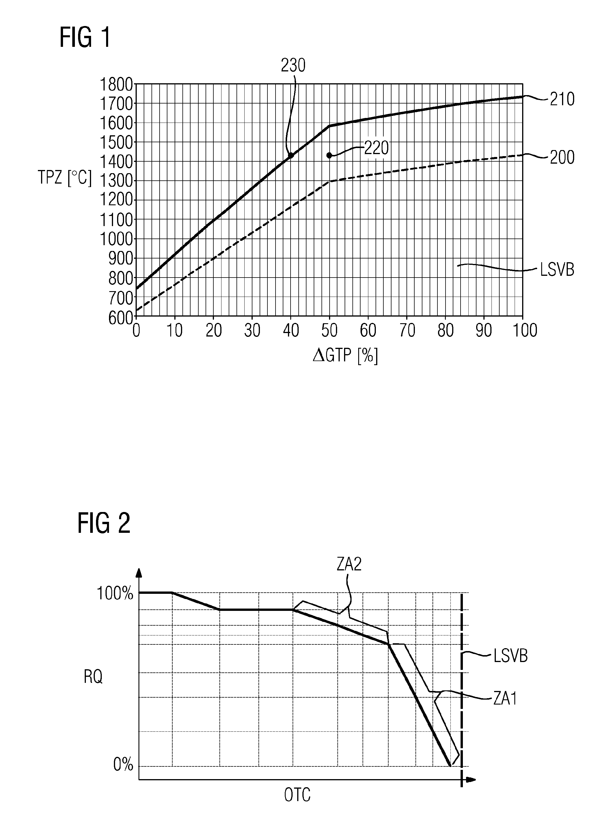
[0042]FIG. 1 shows a diagrammatic representation of the profile of the primary zone temperature TPZ (in ° C.) as a function of the relative gas turbine power AGTP (in %). In this case, two fundamentally different modes of operation of the gas turbine are represented, namely one with a fully closed bypass flow channel (operating mode 200) and one with a fully open bypass flow channel (operating mode 210). A flatter profile in the region of the guide vane adjustment range LSVB over which the gas turbine can be operated with conventional partial load operation by suitable adjustment of the guide vanes in the guide vane adjustment range LSVB at different partial load powers, can be seen clearly for the two operating modes 200 and 210. Support of the partial load operation below this guide vane adjustment range LSVB by adjusting the guide vanes is, however, no longer possible. The ranges available to the invention preferably relate to these ranges lying below. They consequently lie betwe...


PUM


Abstract

A gas turbine has a compressor providing compressed air, a combustion chamber provided with a burner, and an expansion turbine, wherein a bypass flow channel is also provided designed to supply compressed air past the burner and to supply a hot gas flow generated in the combustion chamber during operation of the gas turbine. The opening cross section of the bypass flow channel can be adjusted, and an adjustment unit is designed to adjust the opening cross section of the bypass flow channel such that the modification speed of the opening cross section is selected such that the relative combustion chamber pressure drop or a material temperature of the combustion chamber is substantially constant, in particular that the relative combustion chamber pressure drop or the material temperature of the combustion chamber does not vary by more than 10%.

Description

CROSS REFERENCE TO RELATED APPLICATIONS[0001]This application is the US National Stage of International Application No. PCT / EP2014 / 072703 filed Oct. 23, 2014, and claims the benefit thereof. The International Application claims the benefit of European Application No. EP13190849 filed Oct. 30, 2013. All of the applications are incorporated by reference herein in their entirety.FIELD OF INVENTION[0002]The present invention relates to a method for operating at partial load a gas turbine which comprises a compressor for providing compressor air, a combustion chamber provided with a burner, and an expansion turbine, a bypass flow channel furthermore being provided, which is configured in order to deliver compressor air past the burner and to a hot gas flow generated in the combustion chamber during gas turbine operation. The present invention also relates to such a gas turbine.BACKGROUND OF INVENTION[0003]Gas turbines can typically be operated only in a restricted way in their power rang...

Claims


Application Information

Patent Timeline
IPC IPC(8): F02C9/18F01D17/14F04D19/02F02C3/04F01D5/02
CPCF02C9/18F02C3/04F01D5/021F05D2260/606F01D17/145F05D2220/32F05D2240/35F04D19/02F05D2270/08F05D2270/303F23R3/26F23N2241/20Y02E20/16F02C7/042F02C7/18F02C9/52F05D2270/112F23R3/04F23R2900/03043F23R2900/03342
Inventor ENGLER, THORSTENGUTERMUTH, MANUELKERSTIENS, THOMASKLEINENHAMMANN, MATTHIASKNUWER, NORBERTSUSELBECK, KAITERTILT, MARCWAGNER, ULRICHWEIDNER, FRANK
Owner SIEMENS ENERGY GLOBAL GMBH & CO KG
Learn More