
Method, Apparatus and System for Using Free-Electron Laser Compatible EUV Beam for Semiconductor Wafer Metrology

a free-electron laser and metrology technology, applied in the direction of laser details, electrical equipment, electric discharge tubes, etc., can solve the problems of insufficient hvm general power, lack of natural active lasing medium to produce euv light, and state of the art lack of efficient means for producing hvm compatible euv power for semiconductor manufacturing

Active Publication Date: 2016-09-15
GLOBALFOUNDRIES US INC
View PDF2 Cites 6 Cited by
  • Summary
  • Abstract
  • Description
  • Claims
  • Application Information

AI Technical Summary

Benefits of technology

This patent is about a system and method for producing and using synchrotron radiation for metrology tools. The system includes a beam that has a bend in its electron path, which produces synchrotron radiation. This radiation is then directed to a metrology tool for inspection. The technical effects of this invention include improved methods and apparatus for producing and using synchrotron radiation for metrology tools, which can provide more accurate and reliable results.

Problems solved by technology

Currently available lasers, e.g., argon-fluoride lasers, having sufficient power for HVM generally lack a natural active lasing medium to produce EUV light.
However, the state of the art lacks an efficient means for producing HVM compatible EUV power for semiconductor manufacturing.
Moreover, the prior art lacks an efficient methodology for utilizing energy intrinsically generated by high power lasers for high-resolution inspection / metrology.
The prior art designs of such lasers are not conducive for harnessing intrinsic energy from generating the beams for manufacturing-related purposes, such as metrology data acquisition and analysis.
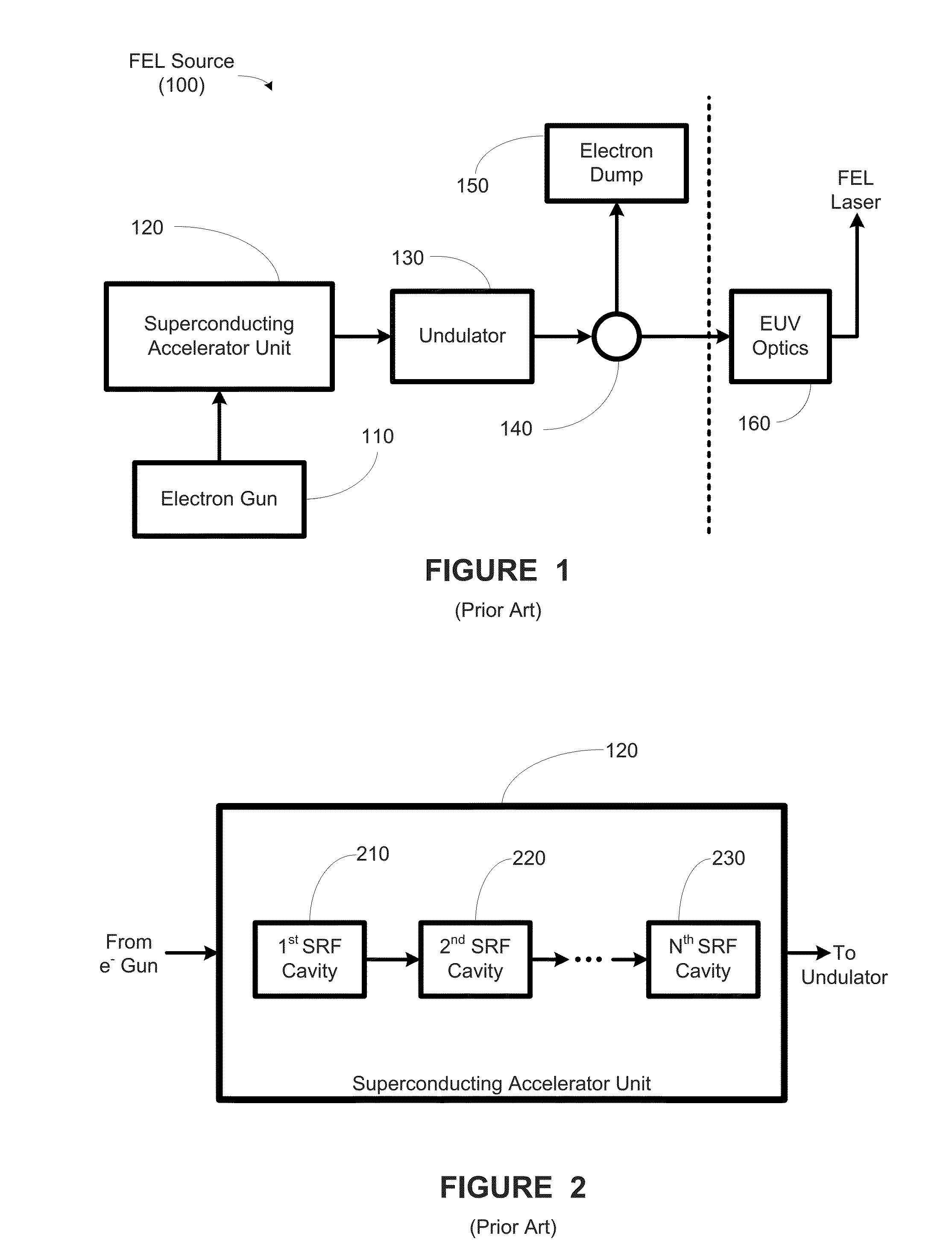
Further, the real estate required to house the large state of the art FEL sources, bury the FEL sources 100, and place it outside the minimum distance from the fab is a substantial undertaking and costly.
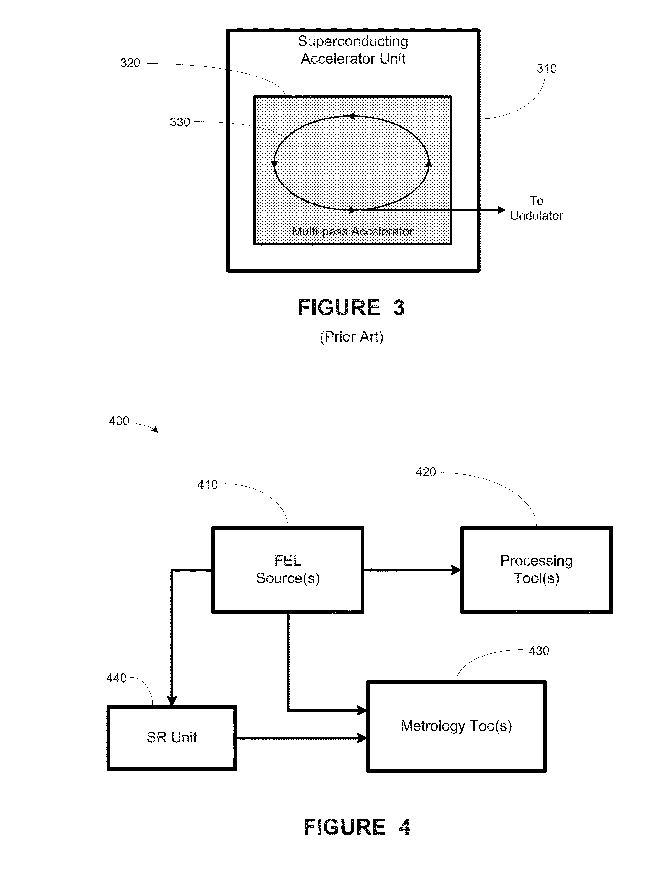
An appreciable amount of energy is generated and lost at each of the bends of the electron path.
The state of the art lacks an efficient means for harnessing this energy.

Method used


Image

  • Method, Apparatus and System for Using Free-Electron Laser Compatible EUV Beam for Semiconductor Wafer Metrology
  • Method, Apparatus and System for Using Free-Electron Laser Compatible EUV Beam for Semiconductor Wafer Metrology
  • Method, Apparatus and System for Using Free-Electron Laser Compatible EUV Beam for Semiconductor Wafer Metrology

Examples


Embodiment Construction

[0030]Various illustrative embodiments of the invention are described below. In the interest of clarity, not all features of an actual implementation are described in this specification. It will of course be appreciated that in the development of any such actual embodiment, numerous implementation-specific decisions must be made to achieve the developers' specific goals, such as compliance with system-related and business-related constraints, which will vary from one implementation to another. Moreover, it will be appreciated that such a development effort might be complex and time-consuming, but would nevertheless be a routine undertaking for those of ordinary skill in the art having the benefit of this disclosure.

[0031]The present subject matter will now be described with reference to the attached figures. Various structures, systems and devices are schematically depicted in the drawings for purposes of explanation only and so as to not obscure the present disclosure with details ...


PUM


Abstract

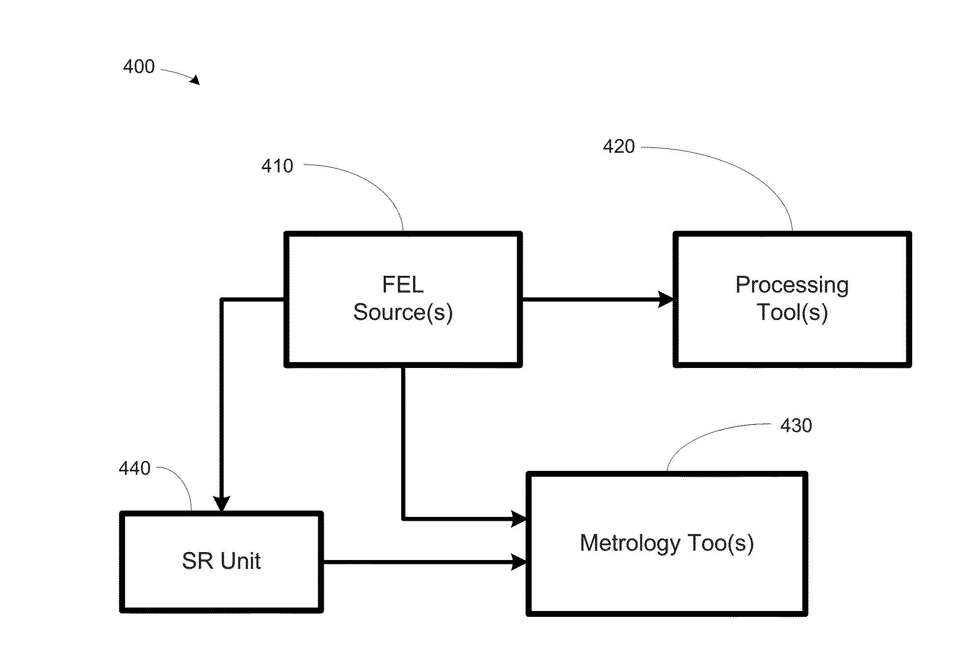
At least one method, apparatus and system for providing capturing synchrotron radiation for a metrology tool, are disclosed. A beam using a first light emitting device is provided. The first light emitting device comprises a first electron path bend. A first synchrotron radiation is provided from the first electron path bend to a first metrology tool configured to perform a metrology inspection using the first synchrotron radiation.

Description

FIELD OF THE INVENTION[0001]Generally, the present disclosure relates to using optics for the manufacture of sophisticated semiconductor devices using, and, more specifically, to various methods and structures for using free-electron laser compatible EUV beam for semiconductor wafer metrology.DESCRIPTION OF THE RELATED ART[0002]The technology explosion in the manufacturing industry has resulted in many new and innovative manufacturing, testing, and analysis processes. Today's manufacturing processes, particularly semiconductor manufacturing processes, call for a large number of important steps as well as analysis of the results of the manufacturing processes. These process and analyses steps are usually vital, and therefore, require a number of inputs that are generally fine-tuned to maintain proper manufacturing control.[0003]The manufacture of semiconductor devices requires a number of discrete process steps to create a packaged semiconductor device from raw semiconductor material...

Claims


Application Information

Patent Timeline
Patent Type & Authority Applications(United States)
IPC IPC(8): H05G2/00
CPCH05G2/008H05G2/00H01S3/0903
Inventor HOSLER, ERIK ROBERTMANGAT, PAWITTER J.S.
Owner GLOBALFOUNDRIES US INC
Learn More