Optical element and lighting device with an optical element
- Summary
- Abstract
- Description
- Claims
- Application Information
AI Technical Summary
Benefits of technology
Problems solved by technology
Method used
Image
Examples
Embodiment Construction
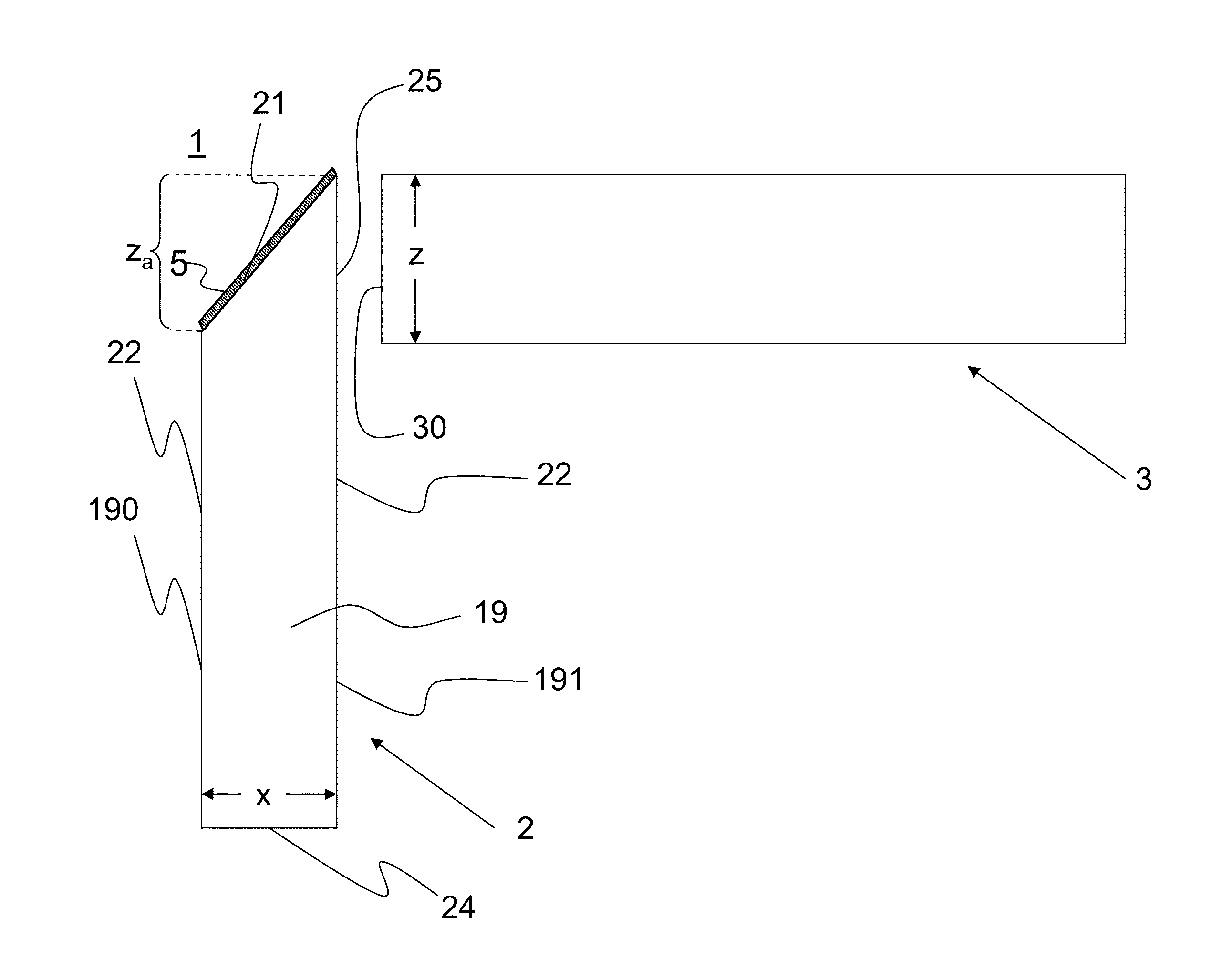
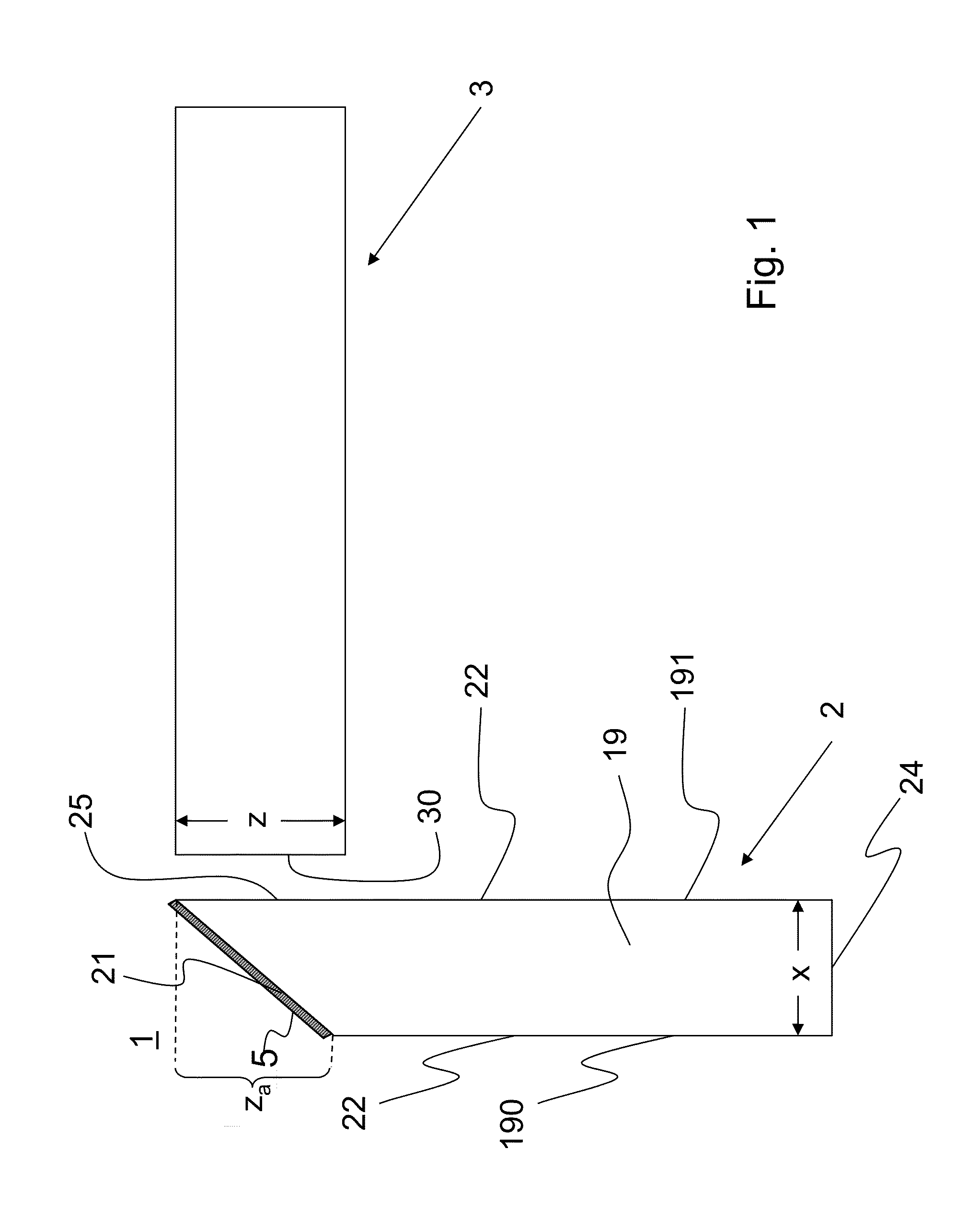
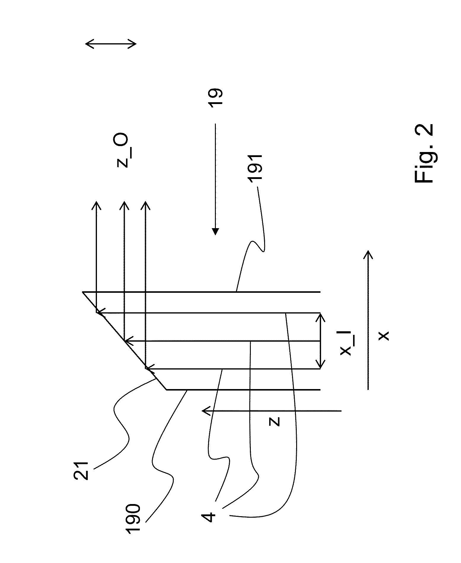
[0045]FIG. 1 schematically illustrates an optical arrangement 1 according to the invention which comprises a first optical element 2 and a second optical element 3. The first optical element 2 is a light guide 19 having walls 22, a light entry area 24, and a light exit area 25. Light exit area 25 is located opposite an inclined bevel face 21 at which the light is deflected by reflection. Generally, without being limited to the particular embodiment illustrated in FIG. 1, the bevel face may be provided as a mirror face for this purpose. It may comprise a dichroic or a metallic coating (e.g. of aluminum or silver), and the metallic coating may optionally be protected against corrosion by a further layer (e.g. SiO2). The mirror function may as well be achieved by adhesively bonding a mirror or a reflective foil.
[0046]A mirror function of the bevel face is particularly preferred for all embodiments. With a mirror face 5 at bevel face 21, even those rays are reflected for which the condi...
PUM
 Abstract
Description
Claims
Application Information
 - R&D
- Intellectual Property
- Life Sciences
- Materials
- Tech Scout
- Unparalleled Data Quality
- Higher Quality Content
- 60% Fewer Hallucinations
Browse by: Latest US Patents, China's latest patents, Technical Efficacy Thesaurus, Application Domain, Technology Topic, Popular Technical Reports.
© 2025 PatSnap. All rights reserved.Legal|Privacy policy|Modern Slavery Act Transparency Statement|Sitemap|About US| Contact US: help@patsnap.com


