Motor assembly with coaxial shafts
a technology of coaxial shafts and motors, which is applied in the direction of dynamo-electric components, synchronous generators, dynamo-electric machines, etc., can solve the problems of reducing the coupling strength between the two motors, the friction force between the boss and the recess needs to be lowered, and the stator and the rotor cannot be connected, so as to achieve high coupling and assembly accuracy, improve the dimensional accuracy of the bearing, and simple configuration
- Summary
- Abstract
- Description
- Claims
- Application Information
AI Technical Summary
Benefits of technology
Problems solved by technology
Method used
Image
Examples
first embodiment
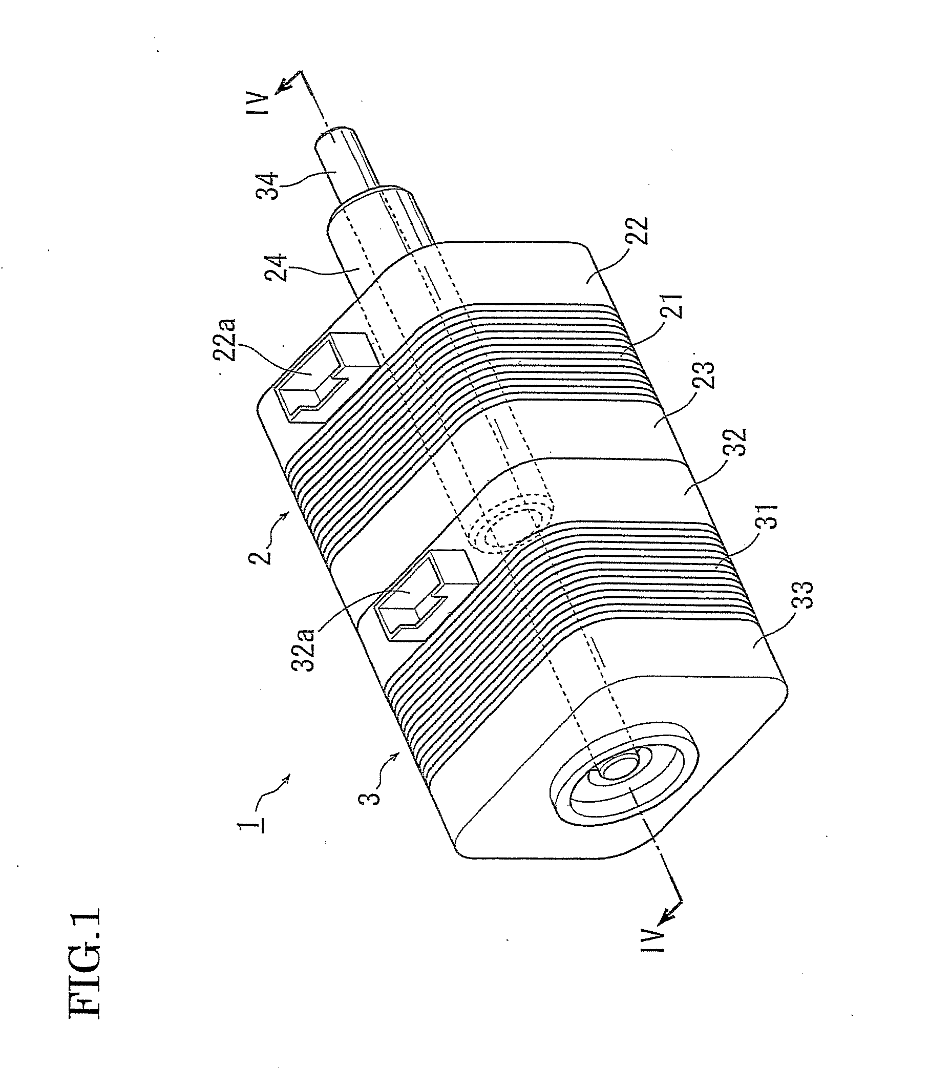
[0027]FIG. 1 is a perspective view of a motor assembly 1 according to the present invention.
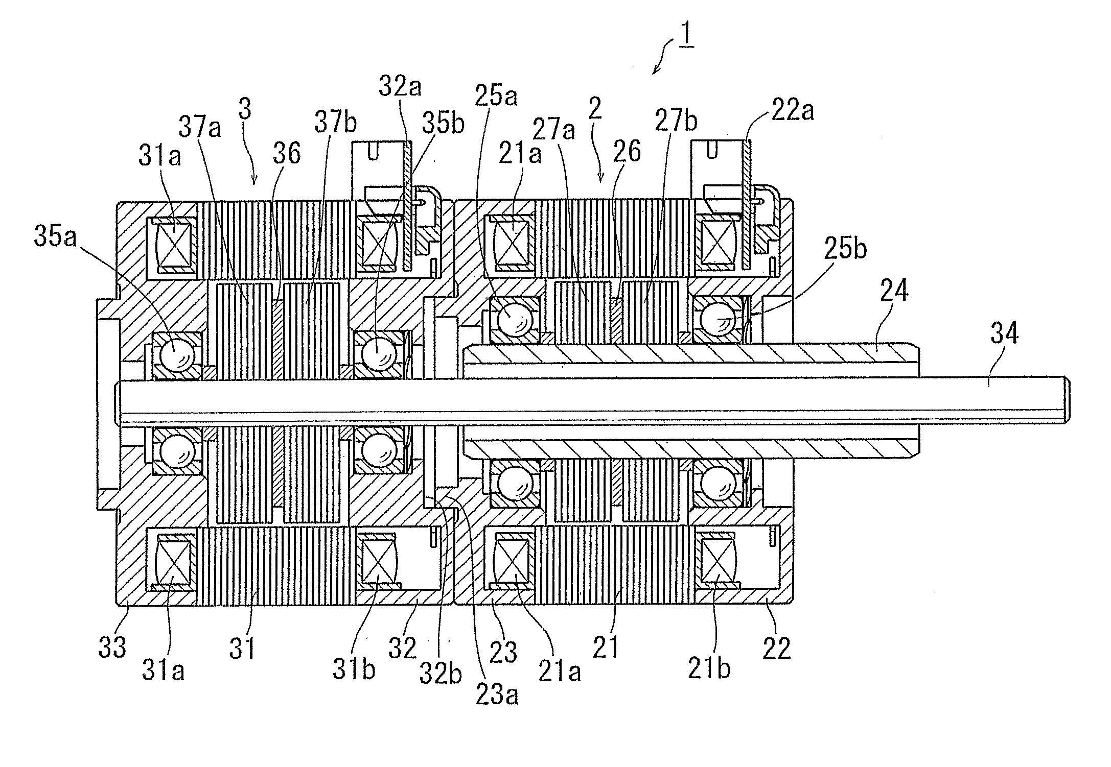
[0028]The motor assembly 1 of the first embodiment includes a first motor 2 and a second motor 3, which are coaxially coupled to each other. The first motor 2 has a rotary shaft 24 and the second motor 3 has a rotary shaft 34.
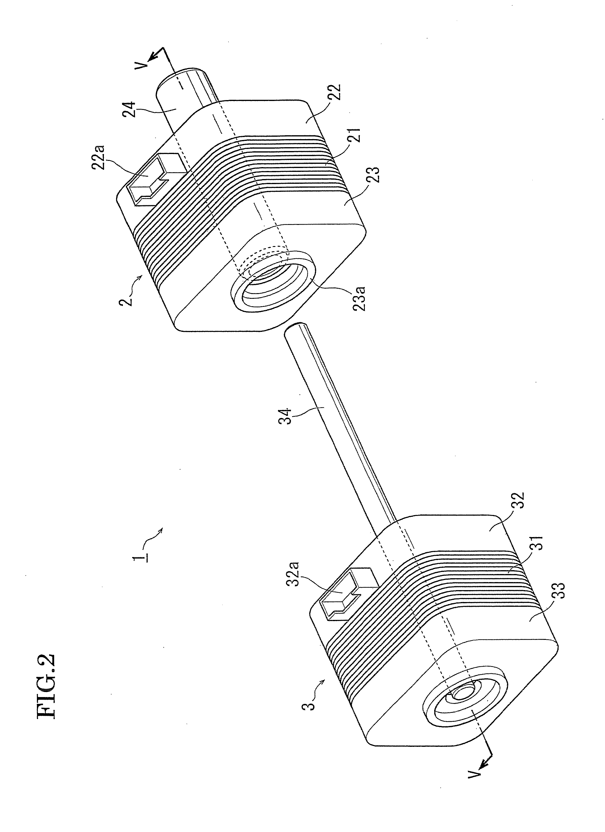
[0029]FIG. 2 is a perspective view of the motor assembly 1 shown in FIG. 1 which is disassembled into the first and second motors 2 and 3. FIG. 3 shows the motor assembly 1 in the same disassembled state as FIG. 2 but viewed from a different angle so that the first motor 2 is located closer to the viewer.
[0030]Referring to FIGS. 2 and 3, the first motor 2 includes a stator stack 21 constructed of laminated electromagnetic steel plates, a front flange 23 as a front housing located axially forward of the stator stack 21 and a rear flange 22 as a rear housing located axially rearward of the stator stack 21. The rear flange 22 is provided with a connector 22a having a termin...
second embodiment
[0038]the present invention will be described below with reference to FIG. 6 which is a perspective view of a motor assembly 100. FIG. 7 is a cross-sectional view of the motor assembly 100 of FIG. 6 taken along line VII-VII.
[0039]In the motor assembly 1 shown in FIG. 1, the rotary shafts 24 and 34 extend out from the rear flange 22 thus constituting output shafts of the motor assembly 1. On the other hand, in the motor assembly 100 of FIG. 6, rotary shafts of respective motors extend out in an opposite direction compared to the motor assembly 1 shown in FIG. 1.
[0040]The motor assembly 100 according to the second embodiment includes a first motor 102 and a second motor 103 coaxially coupled to each other. The first motor 102 has a rotary shaft 124 and the second motor 103 has a rotary shaft 134.
[0041]Referring to FIGS. 6 and 7, the first motor 102 includes a stator stack 121 constructed of laminated electromagnetic steel plates, a front flange 123 as a front housing located axially f...
third embodiment
[0048]the present invention is shown in FIG. 8 which is a perspective view of a motor assembly 200. FIG. 9 is a cross-sectional view of the motor assembly 200 of FIG. 8 taken along line IX-IX.
[0049]The motor assembly 200 includes three motors, specifically a first motor 202, a second motor 203 and a third motor 204 coaxially coupled to one another.
[0050]The first motor 202 has a rotary shaft 224, the second motor 203 has a rotary shaft 234 and the third motor 204 has a rotary shaft 244.
[0051]Referring to FIGS. 8 and 9, the first motor 202 includes a stator stack 221 constructed of laminated electromagnetic steel plates, a front flange 223 as a front housing located axially forward of the stator stack 221, a rear flange 222 as a rear housing located axially rearward of the stator stack 221 and ball bearings 225a and 225b. The rear flange 222 is provided with a connector 222a having a terminal for supplying electric power to the first motor 202 and the front flange 223 is provided wit...
PUM
 Abstract
Description
Claims
Application Information
 - R&D
- Intellectual Property
- Life Sciences
- Materials
- Tech Scout
- Unparalleled Data Quality
- Higher Quality Content
- 60% Fewer Hallucinations
Browse by: Latest US Patents, China's latest patents, Technical Efficacy Thesaurus, Application Domain, Technology Topic, Popular Technical Reports.
© 2025 PatSnap. All rights reserved.Legal|Privacy policy|Modern Slavery Act Transparency Statement|Sitemap|About US| Contact US: help@patsnap.com


