Image forming apparatus

a technology of image forming apparatus and photoreceptor drum, which is applied in the direction of electrographic process apparatus, instruments, corona discharge, etc., can solve the problems of poor image quality, accelerated abrasion of the photoreceptor drum, and contamination of the second transfer roller, so as to shorten the waiting time of users

Active Publication Date: 2016-09-01
KONICA MINOLTA INC
View PDF0 Cites 8 Cited by
  • Summary
  • Abstract
  • Description
  • Claims
  • Application Information

AI Technical Summary

Benefits of technology

The present invention aims to reduce the waiting time for users when determining the peak-to-peak voltage needed for various processes. The technical effect is to shorten the time from start to finish for users, making the image forming apparatus more efficient and effective.

Problems solved by technology

The toner moves to a second transfer roller via an intermediate transfer belt, which causes contamination of the second transfer roller.
If the peak-to-peak voltage Vpp of the alternating voltage Vaci is too small, it results in poor-quality image formation.
On the other hand, if the peak-to-peak voltage Vpp of the alternating voltage Vaci is too great, it accelerates abrasion of the photoreceptor drum.
If the first charging voltage determination process is carried out for these processes, it will keep users waiting for a long time.

Method used


Image

  • Image forming apparatus
  • Image forming apparatus
  • Image forming apparatus

Examples


Embodiment Construction

[0031]Some preferred embodiments of the present invention will hereinafter be described with reference to the drawings.

1. Definitions

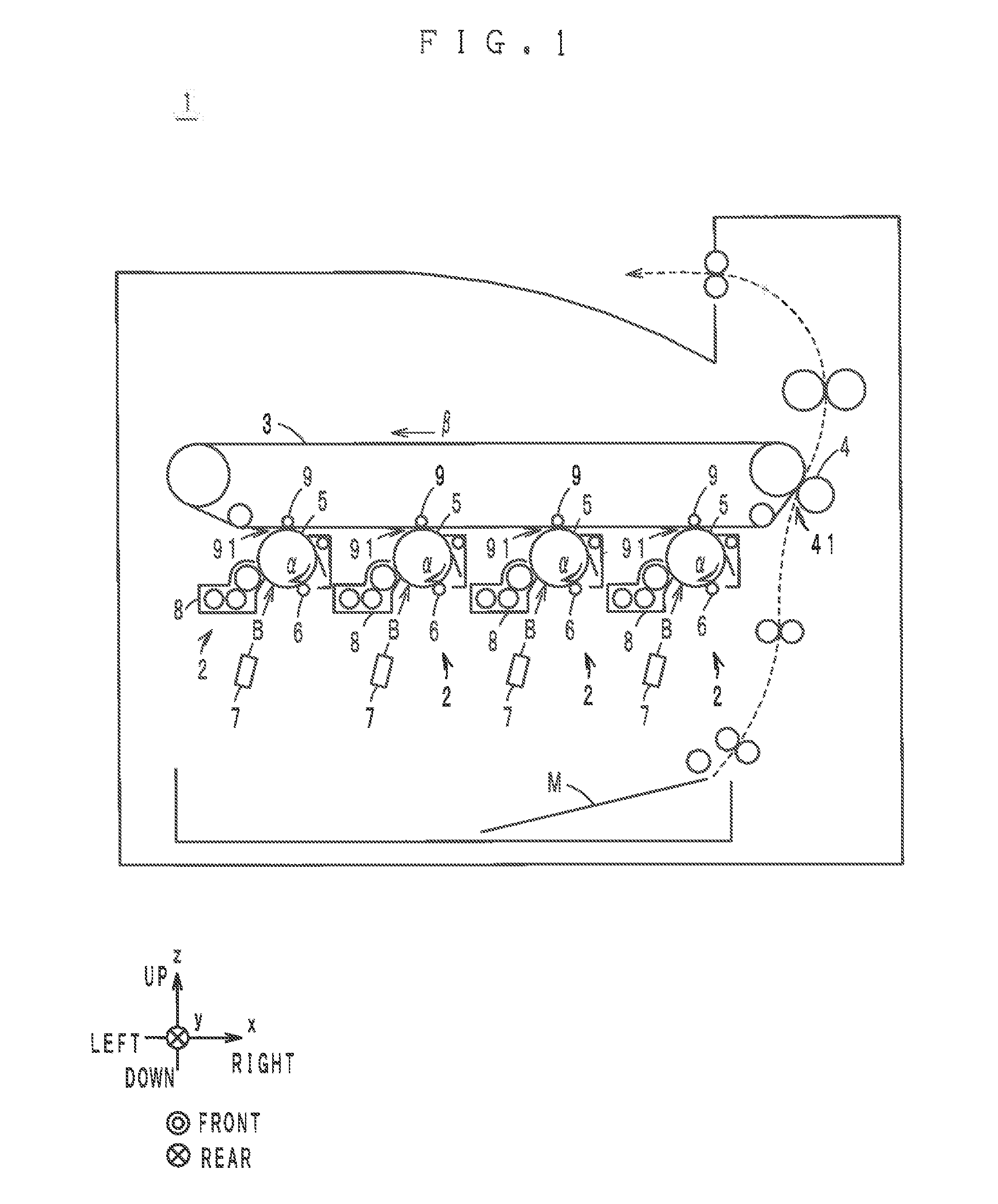
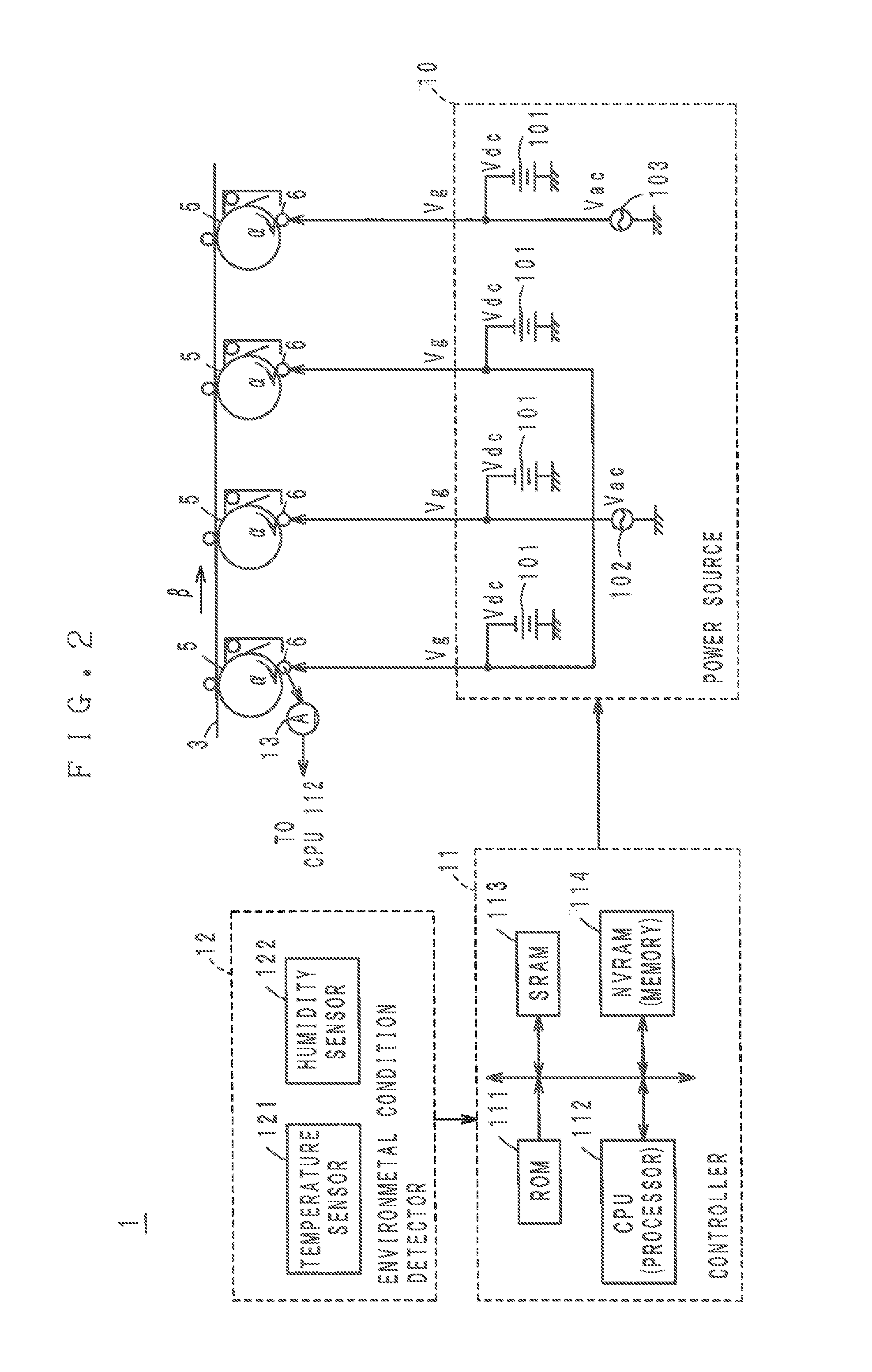
[0032]In some of the drawings, x-direction, y-direction and z-direction that are perpendicular to one another are indicated. The x-direction and the z-direction indicate the right-left direction and the up-down direction of an image forming apparatus 1. The y-direction indicates the front-rear direction of the image forming apparatus 1.

2. General Structure of Image Forming Apparatus and Printing Process

[0033]The image forming apparatus 1 illustrated in FIGS. 1 and 2 is, for example, a copying machine, a printer, a facsimile or a multifunction peripheral capable of functioning as these machines. The image forming apparatus 1 prints an image (typically, a full-color image or a monochromatic image) on a print medium (for example, a sheet of paper or an OHP sheet) M by an electrophotographic tandem method. For this purpose, the image forming apparatus 1 co...


PUM


Abstract

An image forming apparatus has: an image supporting member; a charger in proximity to the image supporting member; a power source unit configured to apply charging voltages to the charger sequentially, the charging voltages including alternating voltages having different peak-to-peak voltages, respectively; an amperometric detector configured to detect values of alternating currents flowing in the charger during application of the charging voltages; and a processor configured to carry out a first charging voltage determination process or a second charging voltage determination process requiring a shorter time than the first charging voltage determination process selectively based on a detection result of the amperometric detector. The processor carries out the first charging voltage determination process or the second charging voltage determination process selectively in accordance with a difference between an ambient temperature at a previous time of carrying out the first charging voltage determination process and a current ambient temperature.

Description

[0001]The present invention claims benefit of priority to Japanese Patent Application No. 2015-036271 filed Feb. 26, 2015, the content of which is incorporated herein by reference.BACKGROUND OF THE INVENTION[0002]1. Field of the Invention[0003]The present invention relates to an image forming apparatus comprising a proximity charger to be impressed with a superimposed voltage of a DC voltage and an AC voltage.[0004]2. Description of Related Art[0005]Recently, for charging in an image forming apparatus, a proximity charging method is mainly adopted. In the proximity charging method, for example, a roller-type charger is provided in proximity to the surface of a photoreceptor drum so as to be in contact or out of contact with the surface of the photoreceptor drum. A superimposed voltage of a DC voltage and an AC voltage is applied to the charger so that the charger can charge the surface of the photoreceptor drum uniformly.[0006]It is known that the charged potential Vs of the surface...

Claims


Application Information

Patent Timeline
Patent Type & Authority Applications(United States)
IPC IPC(8): G03G15/02G03G21/20
CPCG03G21/20G03G15/0266G03G2215/00772G03G2215/00776G03G2215/0132
Inventor KATO, TOMOHIROKOBORI, KAZUKISHIRAI, HIROHISAMURATA, HISASHIKIMURA, MASATO
Owner KONICA MINOLTA INC
Why Eureka
Try Eureka