
Electronic control apparatus, motor control apparatus and electric fluid pump

a technology of electric fluid pump and control apparatus, which is applied in the direction of casing/cabinet/drawer details, casing/cabinet/drawer details, electric apparatus, etc., can solve the problems of electrical discharge impairing the function of electric devices and damage to electric devices

Inactive Publication Date: 2016-08-25
HITACHI AUTOMOTIVE SYST LTD
View PDF3 Cites 20 Cited by
  • Summary
  • Abstract
  • Description
  • Claims
  • Application Information

AI Technical Summary

Benefits of technology

The patent is about finding a way to release static charge from a vehicle's metallic cover without adding any new component parts or assembly steps, which could increase production costs. The goal is to find a way to protect the exposed coated wire from damage and improve the durability of the entire system. This invention aims to provide a simpler solution for relieving static charge and ensuring the proper functioning of electronic control, motor control, and electric fluid pumps.

Problems solved by technology

The static electricity of the high voltage may cause electric discharge impairing the function of electric devices in the drive control section inside the cover and even damage the electric devices in an extreme case.

Method used


Image

  • Electronic control apparatus, motor control apparatus and electric fluid pump
  • Electronic control apparatus, motor control apparatus and electric fluid pump
  • Electronic control apparatus, motor control apparatus and electric fluid pump

Examples


first embodiment

[0027]In the following embodiment, the present invention is applied to a motor control apparatus including an electric fluid pump and a drive control device united as a unit. However, the present invention is not limited to the motor control apparatus of this type. The present invention is applicable to various electronic control apparatus and to various motor control apparatus such as an electric power steering apparatus, for example.

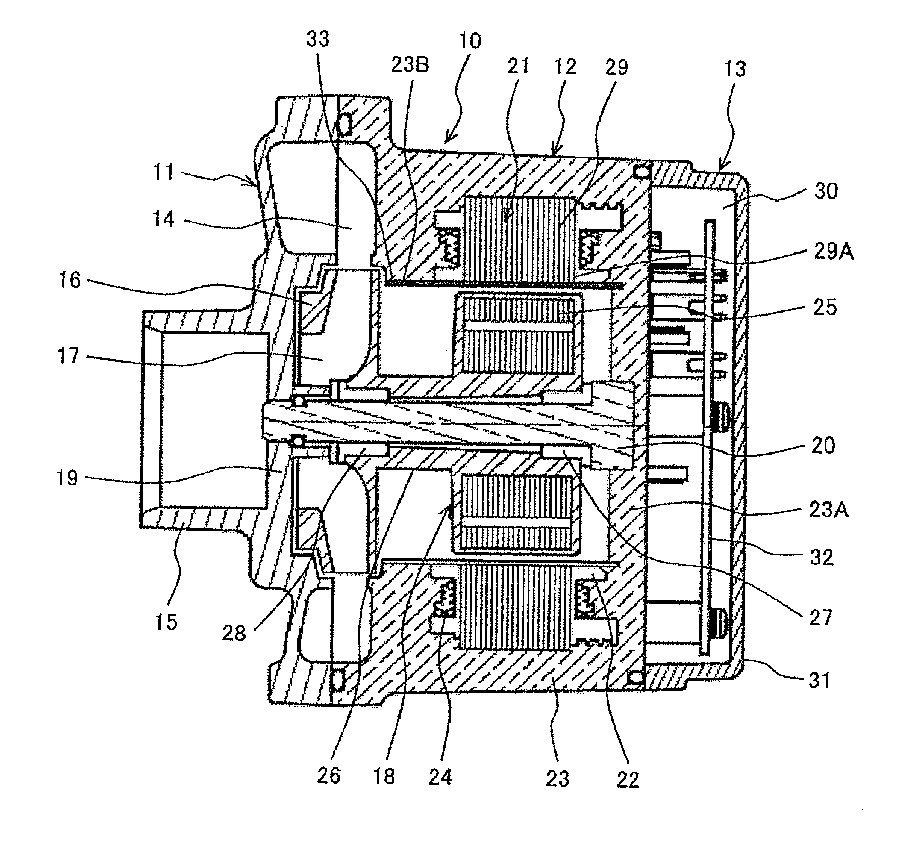
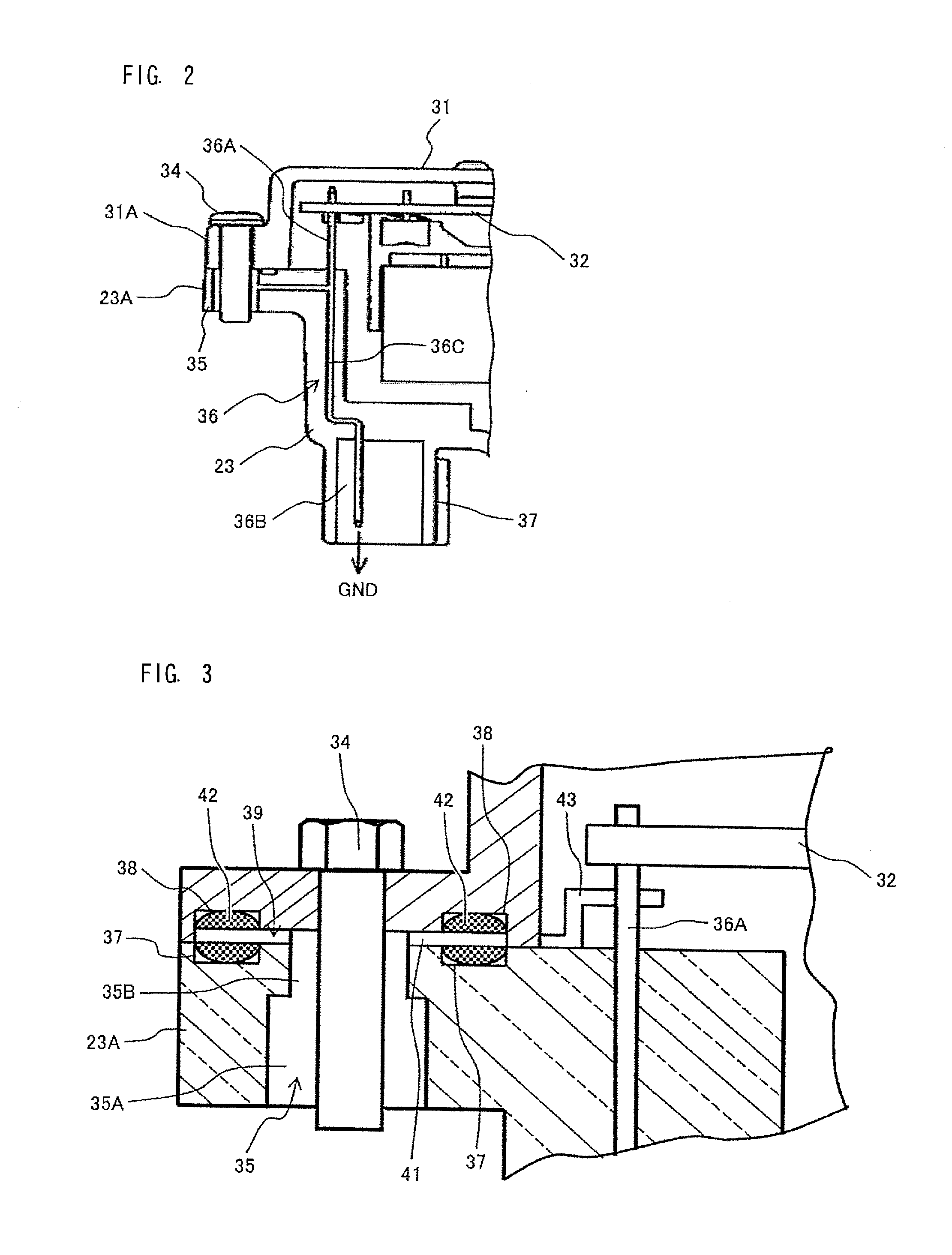
[0028]FIG. 1 is a sectional view showing the overall structure of an electric fluid pump according to a first embodiment of the present invention, and FIGS. 2-7 are views more in detail. The electric fluid pump shown in FIG. 1 is a cooling pump which uses a cooling water as an operating fluid, and which is adapted to be incorporated in a cooling water circulating circuit connected with a heat exchanger in the form of a radiator. For example, this electric fluid pump can be used as water pump for supplying the cooling water to an internal combustion eng...

second embodiment

[0084]FIG. 8 shows a second embodiment of the present invention. In the second embodiment, a drive control section 53 is enclosed in a casing 50 as an electronic control apparatus not integrated with another apparatus such as a motor or a fluid pump whereas the drive control section 13 according to the first embodiment is integrated with the motor and / or the pump. The arrangement for transferring the static electricity toward the ground is basically the same as the arrangement in the first embodiment, so that the explanation is simplified.

[0085]The casing 50 of the electronic control apparatus shown in FIG. 8 includes a controller housing 51 and a controller cover 52. The drive control section 53 is disposed in the inside interspace formed between controller housing 51 and controller cover 52. The drive control section 53 of this example is a driver for supplying a driving current to an electric component such as an electric motor, and includes a control board 54 including electric ...


PUM


Abstract

An electronic control apparatus comprises a housing of synthetic resin, a cover of metallic material, fixed to the housing by a fastening bolt, and an electronic control section enclosed in an interspace formed between the housing and the cover. A conductive gasket is interposed between a joint surface of the housing and a joint surface of the cover, and arranged to ground the cover electrically through the conductive gasket, to relieve static electricity from the metallic cover to a ground or a main body of a vehicle.

Description

TECHNICAL FIELD[0001]The present invention relates to control apparatus such as electronic control apparatus, motor control apparatus and electric fluid motor.BACKGROUND ART[0002]Recently, with increase in demand for lower fuel consumption of motor vehicles, there is a tendency to use a motor such as brushless motor widely in various control mechanisms in the motor vehicles, and the motor is integrated with a drive control device for controlling the motor, into a compact unit.[0003]For example, the function of idle stop is widely used in motor vehicles and the practical use of hybrid vehicles is spreading. In these vehicles, when an internal combustion engine is stopped, a mechanical fluid pump driven by the engine is also stopped. Therefore, another source for driving a fluid pump is required besides the internal combustion engine. Furthermore, electric vehicles and hybrid vehicles require a driving motor, its drive control apparatus and a cooling water pump for cooling a battery. ...

Claims


Application Information

Patent Timeline
Patent Type & Authority Applications(United States)
IPC IPC(8): H02K5/08H05K5/03H05K5/02H05K5/06H02K11/33H02K11/40
CPCH02K5/08H02K11/33H05K5/03H05K5/0247H05K5/061H02K11/40F04D13/06H02K5/10H02K5/128H02K7/14H05K9/0015
Inventor TAKARAI, KENYA
Owner HITACHI AUTOMOTIVE SYST LTD
Learn More