Constant velocity joint

a constant velocity, joint technology, applied in the direction of yielding couplings, rotary machine parts, couplings, etc., can solve the problems of reducing the durability of the outer member b>1/b>, reducing the durability of the outer member, and being highly costly to manufacture, so as to achieve surface pressure acting and increase durability

Inactive Publication Date: 2009-12-15
HONDA MOTOR CO LTD
View PDF34 Cites 6 Cited by
  • Summary
  • Abstract
  • Description
  • Claims
  • Application Information

AI Technical Summary

Benefits of technology

[0034]According to the constant-velocity joint of the present invention, each of first guide grooves held in contact with a corresponding one of balls at a single point has a transverse cross section extending perpendicularly to the axial direction and having a single arc shape, and each of second guide grooves held in contact with a corresponding one of the balls at two points has a transverse cross section extending perpendicularly to the axial direction and having an elliptically arc shape, whereby surface pressure acting on the guide grooves due to contact with the balls is reduced for increased durability compared with the conventional constant-velocity joints.
[0037]Further, in the present invention, a PCD clearance is set in a range from 0 to 100 μm, because if the PCD clearance is smaller than 0 μm, then the balls cannot be assembled in place efficiently and cannot roll smoothly, resulting in poor durability, and if the PCD clearance is in excess of 100 μm, then the contact ellipse of the balls held in contact with the first and second guide grooves protrudes from the shoulders at the groove edges at high load, increasing the surface pressure and cracking the shoulders, with the result that durability is lowered.
[0042]According to the present invention, the ratio V (=T / N) of the diameter N of the balls to the distance T by which the centers (the points H, R) of curvature of the first guide grooves and the second guide grooves is set to satisfy the expression 0.12≦V≦0.14, whereby the balls are effectively prevented from moving onto or cracking and wearing the shoulders at the edges of the first guide grooves and the second guide grooves to make the constant-velocity joint more durable.
[0043]If the ratio V(T / N) of the diameter N to the offset distance T is less than 0.12, then the funnel angle formed between the first guide grooves and the second guide grooves is minimized, allowing the balls to be easily locked when the constant-velocity joint is not in rotation, and also resulting in a reduction in the efficiency with which the constant-velocity joint is assembled. On the other hand, if the ratio V(T / N) of the diameter N to the offset distance T is in excess of 0.14, then since the first guide grooves and the second guide grooves are made shallow, the balls are easily liable to move onto or crack and wear the shoulders at the edges of the first guide grooves and the second guide grooves.
[0049]With this ratio (R / N) of 0.23 or more, a maximum major stress load on the columns between the retaining windows is reduced for increasing the mechanical strength of the retainer. On the other hand, with the ratio (R / N) of 0.45 or less, it is possible to effectively prevent the balls and the inner ring from failing to be assembled due to an excessively large radius of curvature of the corners of the retaining windows.

Problems solved by technology

According to the first and second methods, however, the retainer 4 becomes heavy and has a greater width, and the balls 3 tend to bite into the guide grooves 1b, reducing the durability of the outer member 1.
However, the fixed constant-velocity universal joint disclosed in Japanese Laid-Open Patent Publication No. 2001-330051 is made of up a large number of parts, is highly costly to manufacture, and is difficult to produce in practice.
As the ball grooves in the outer race and the ball grooves in the inner race are offset equal distances from the joint center, the depths of the ball grooves in the outer and inner races are not uniform in the axial direction.
With the structure disclosed in the general document, since the depths of the ball grooves in the outer race and the ball grooves in the inner race are small, when the constant-velocity joint operates at large joint angles or under high loads, the contact ellipse of the balls protrudes from the ball grooves, tending to bring the balls onto shoulders (edges) of the ball grooves, causing the balls to crack or to wear down the shoulders (edges) of the ball grooves, resulting in a reduction in the durability of the constant-velocity joint.
Furthermore, when the constant-velocity joint is placed under a high load, the positions where the ball grooves and the balls contact each other are brought closely to the end of the inner race, and the contact ellipse of the balls protrudes from the ball grooves, thus increasing the contact pressure imposed on the balls grooves by the balls.
If the diameter of the balls is reduced or the size of the constant-velocity joint itself is reduced, and the wall thickness of the retainer, which is the mechanically weakest component, is to be maintained, then the guide grooves in the outer race and the inner race are necessarily of an insufficient depth, and the shoulders of the guide grooves tend to be cracked or worn as described above.
If the PCD gap is too small, then it will be difficult to assemble the balls into the ball tracks, and restraint forces applied to the balls will be too large to allow the balls to make smooth rolling movement.
If the PCD gap is too large, then striking noise will be generated between the balls and the windows of the retainer and the vibration of the joint itself will increase.
However, the above ratio setting is not effective enough to increase the mechanical strength of the retainer.

Method used


Image

  • Constant velocity joint
  • Constant velocity joint
  • Constant velocity joint

Examples


Embodiment Construction

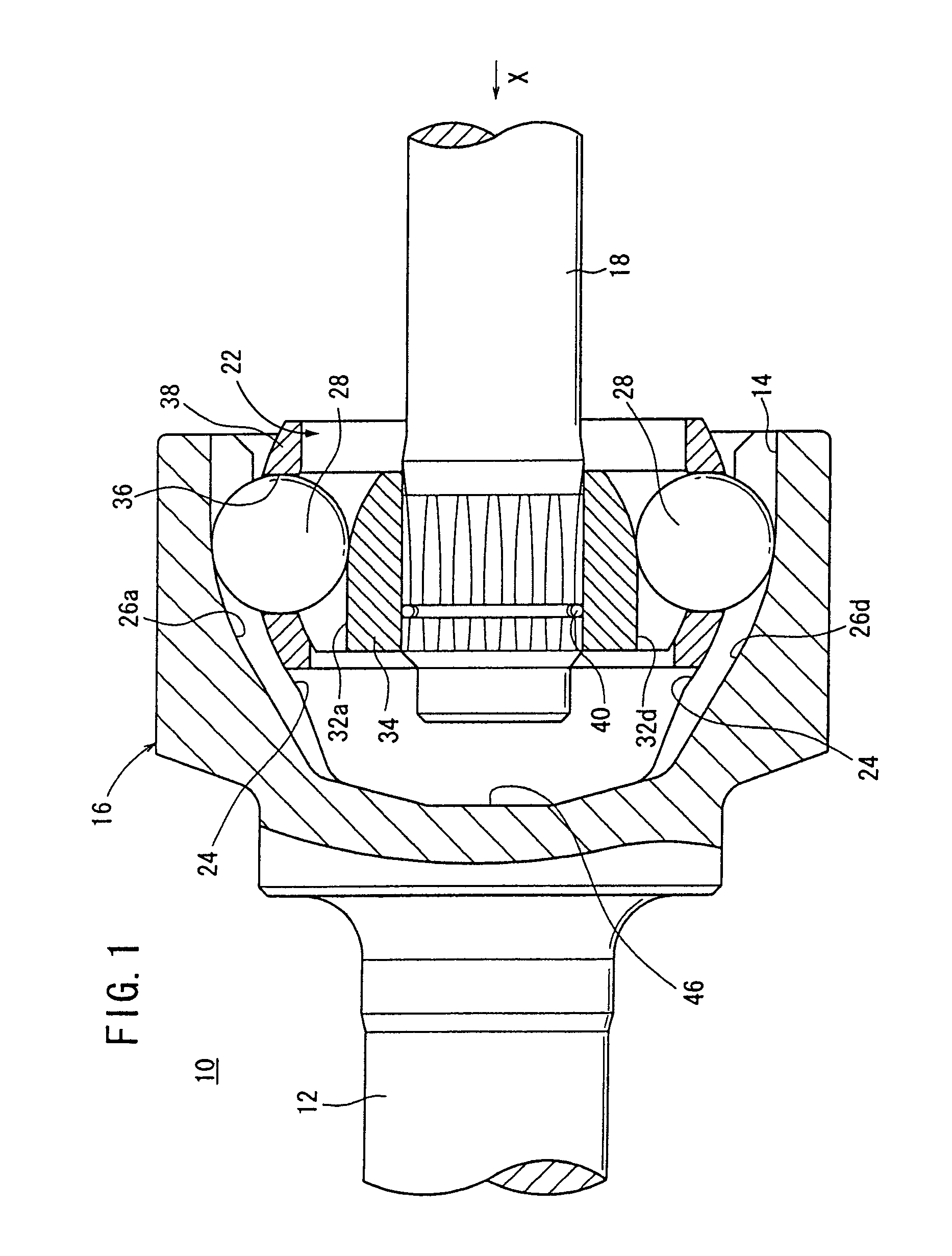
[0078]FIG. 1 shows a constant-velocity joint 10 according to an embodiment of the present invention. In the description which follows, a longitudinal cross section refers to a cross section along the axial direction of a first shaft 12 and a second shaft 18, and a transverse cross section to a cross section perpendicular to the axial direction.

[0079]The constant-velocity joint 10 is basically constructed of a bottomed cylindrical outer cup (outer member) 16 integrally joined to an end of a first shaft 12 and having an opening 14 that opens away from the first shaft 12, and an inner member 22 fixed to an end of a second shaft 18 and housed in the outer cup 16.

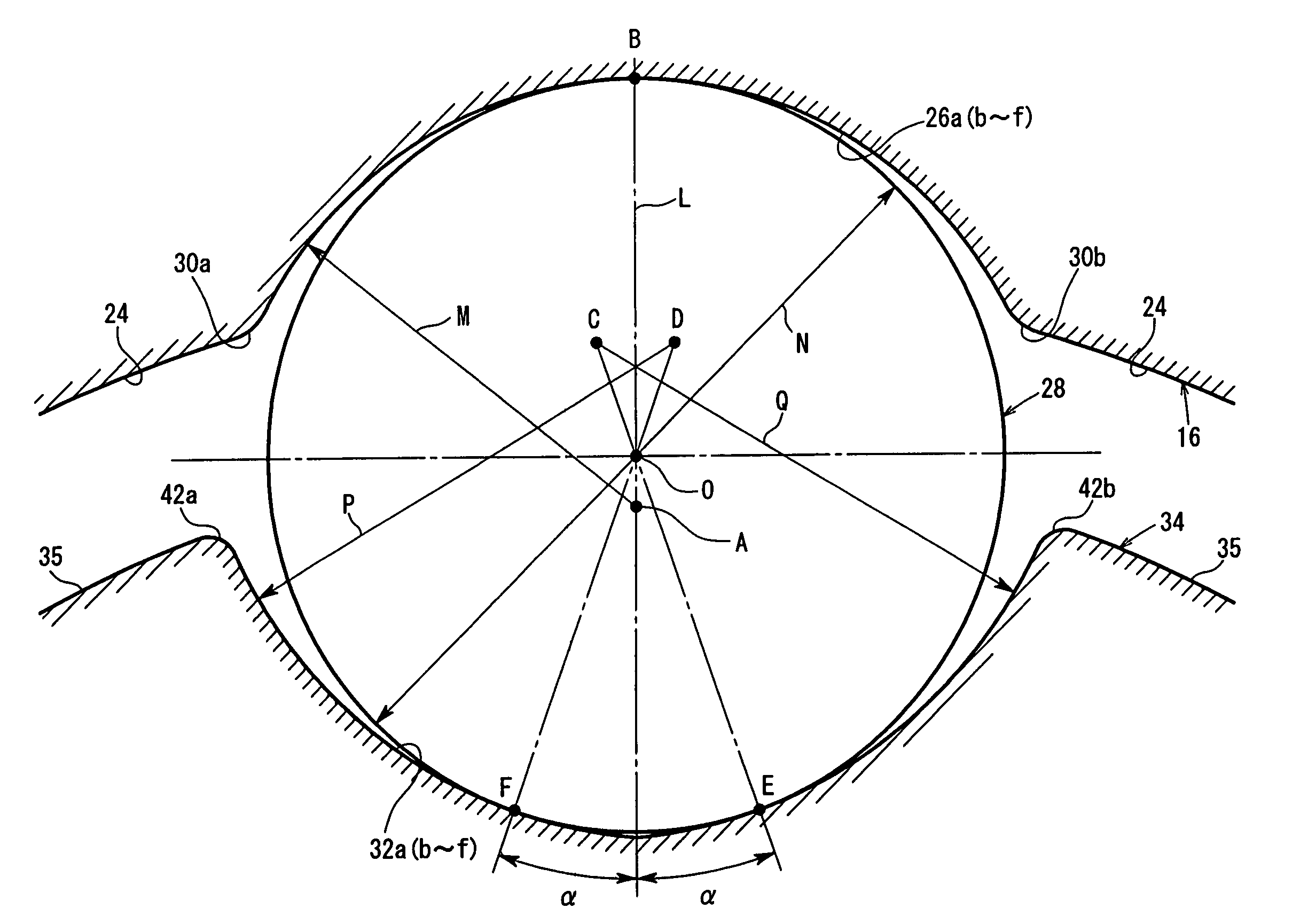
[0080]As shown in FIGS. 1 and 3, the outer cup 16 has a spherical inside-diameter surface 24 on its inner wall. The inside-diameter surface 24 has six first guide grooves 26a through 26f extending in the axial direction and angularly spaced at 60-degree intervals around the axis thereof.

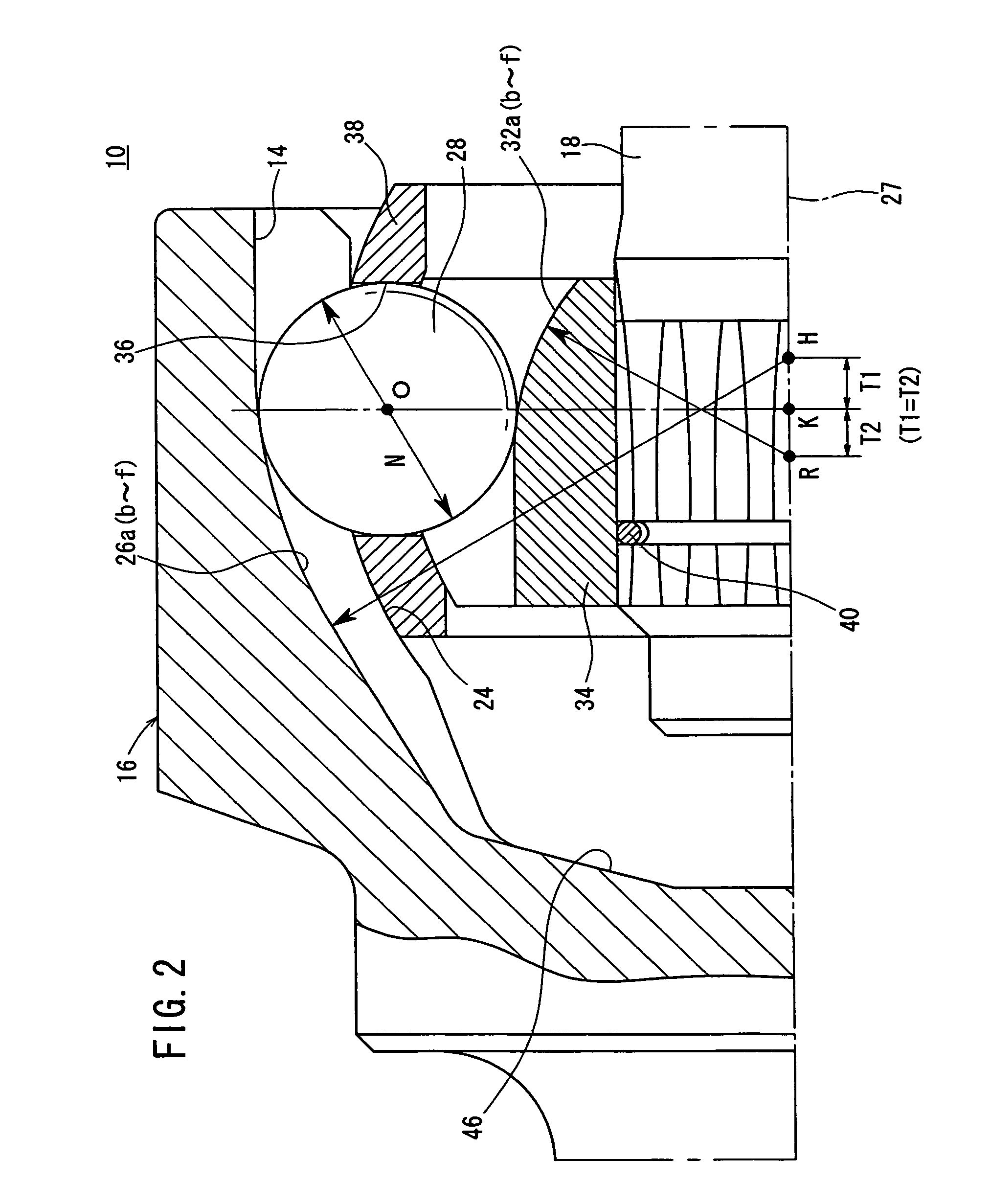
[0081]As shown in FIG. 2, the first guide ...


PUM


Abstract

Lateral cross-sections of first guiding grooves provided in the inner wall surface of an outer cup are formed in a circular arc shape for one point contact with balls, and lateral cross-sections of second guiding grooves provided in the outer wall surface of an inner ring are formed in an elliptic arc shape for two-point contact with the balls. The diameter of a ball and an offset amount between a first and a second groove is set to satisfy the expression of 0.12≦V≦0.14 with V being the ratio of the two values.

Description

TECHNICAL FIELD[0001]The present invention relates to a constant-velocity joint for connecting a transmission shaft to another transmission shaft in an automotive driveline, for example.BACKGROUND ART[0002]Heretofore, automotive drivelines employ a constant-velocity joint for connecting a transmission shaft to another transmission shaft and transmitting rotational power to the axles. In recent years, there has been a growing need for lighter constant-velocity joints and hence smaller constant-velocity joints. The mechanical strength, durability, load capacity, etc. of constant-velocity joints are determined by the basic dimensions of various components of the constant-velocity joints. It is necessary to determine those basic dimensions for smaller constant-velocity joints while maintaining the mechanical strength, durability, load capacity, etc. at desired levels.[0003]Japanese Laid-Open Patent Publication No. 2001-330051 discloses a fixed constant-velocity universal joint having an...

Claims


Application Information

Patent Timeline
Patent Type & Authority Patents(United States)
IPC IPC(8): F16D3/224F16D3/223F16D3/2237
CPCF16D3/223F16D3/2237F16D3/224F16D2003/22309F16D2003/22303Y10S464/906
Inventor NAKAO, SHOUICHIIDO, KAZUKIYOKOYAMA, AKIRA
Owner HONDA MOTOR CO LTD
Why Eureka
Try Eureka