
Optical disc drive

Active Publication Date: 2016-08-25
HITACHI LG DATA STORAGE KOREA
View PDF0 Cites 0 Cited by
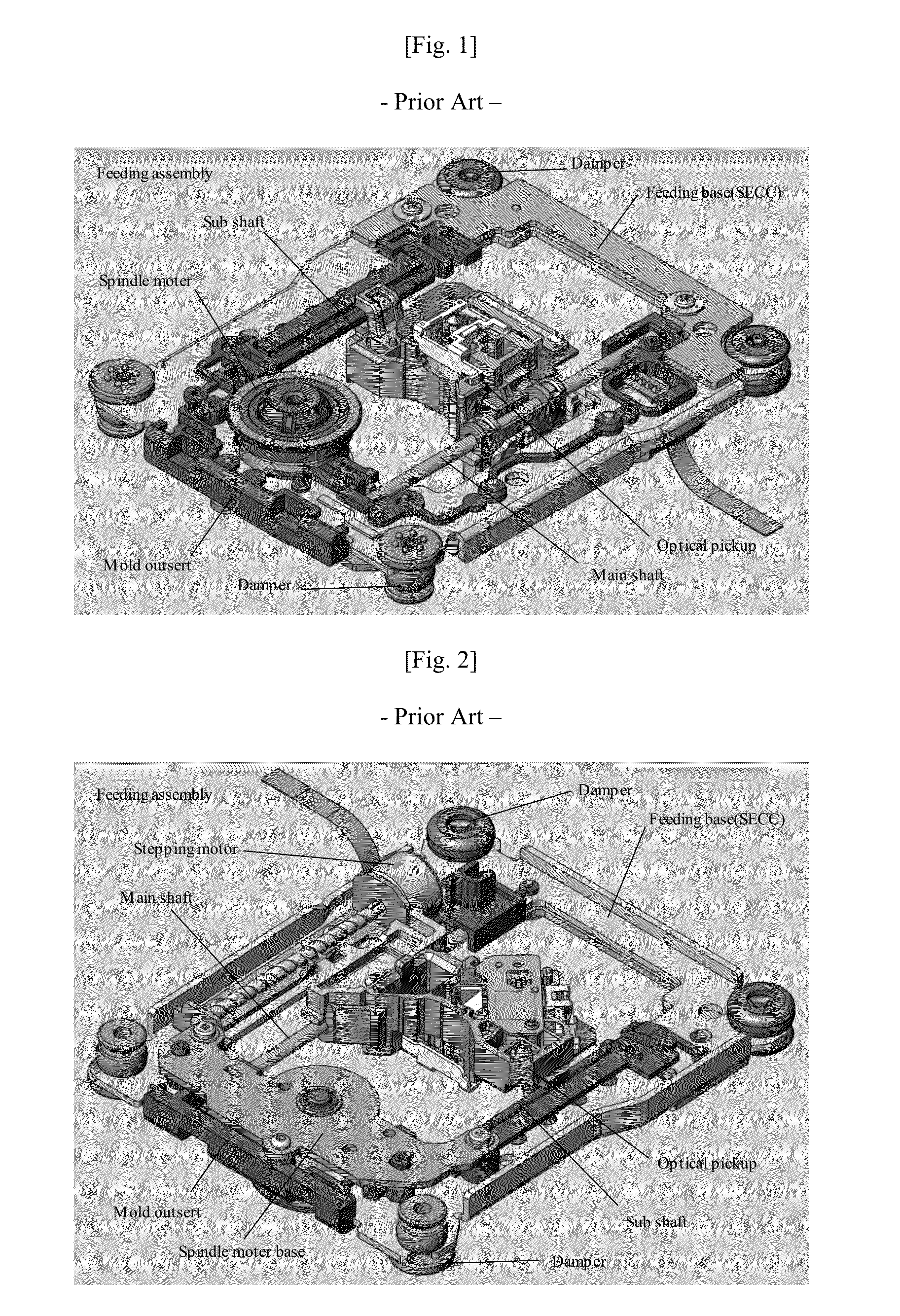
  • Summary
  • Abstract
  • Description
  • Claims
  • Application Information

AI Technical Summary

Benefits of technology

The structure described in this patent is made using a special steel plate called SECC, which is processed with press tools. This structure is different from traditional structures because it has fewer parts, is more cost-effective, and has better quality management because it eliminates the need for a mold part. In simple terms, the invention is a way to make a structure using SECC and press tools, which is more efficient and cost-effective than using a mold.

Problems solved by technology

The method (1) is disadvantageous in that it is difficult to achieve price competitiveness because guide parts for assembling the parts at regular positions are required and thus the number of required parts is increased.
The method (2) is advantageous in that the feeding assembly can be configured using a smaller number of parts because all of the guides for assembling the parts at regular locations are configured in an outsert, but is disadvantageous in that a cost for fabricating the outsert is required.

Method used


Image

  • Optical disc drive
  • Optical disc drive
  • Optical disc drive

Examples


Embodiment Construction

[0029]The above object, characteristics, and merits of the present invention will become more apparent from the following detailed description taken in conjunction with the accompanying drawings. The present invention may be modified in various ways and may have some embodiments. Hereinafter, some exemplary embodiments of the present invention will be illustrated in the accompanying drawings and described in detail. The same reference numerals basically designate the same elements throughout the drawings. Furthermore, in describing the present invention, a detailed description of known functions or elements relating to the present invention will be omitted if it is deemed to make the gist of the present invention unnecessarily vague. Numbers (for example, the first and the second) used to describe the present invention are merely identification symbols for distinguishing one element from the other element.

[0030]Hereinafter, the feeding base of an optical disc drive according to an e...


PUM


Abstract

Disclosed herein are an optical disc drive and a feeding base. The feeding base is coupled to a spindle motor base and a stepping motor base. Main and sub-shafts for guiding inner and outer circumferential movements of an optical pickup unit are mounted on the feed base. The feeding base is made of a steel plate of a rectangular rim shape having an empty center corresponding to a space in which the optical pickup unit moves, the feeding base includes two guides for guiding the coupling location of the spindle motor base, and at least one guide of the two guides is formed by protruding the steel plate to form a funnel shape such that the side cross section of the at least one guide may have a slope section corresponding to a cone and a straight-line section corresponding to a cylinder.

Description

CROSS-REFERENCE TO RELATED APPLICATION[0001]Pursuant to 35 U.S.C. §119(a), this application claims the benefit of earlier filing date and right of priority to Korean Patent Application No. 10-2015-0026503, filed on Feb. 25, 2015, the contents of which are incorporated by reference herein in their entirety.BACKGROUND OF THE INVENTION[0002]1. Field of the Invention[0003]The present invention relates to an optical disc drive and, more particularly, to the structure of the feeding base of an optical disc drive.[0004]2. Discussion of the Related Art[0005]In an optical disc drive, a structure called a feeding assembly is configured so that parts, such as a spindle motor for rotating an optical disc, an optical pickup unit for recording data on an optical disc or playing back data recorded on the optical disc, and a stepping motor for moving the optical pickup unit to the inner and outer circumferential directions of the optical disc, are assembled into a single base. The base in which the...

Claims


Application Information

Patent Timeline
IPC IPC(8): G11B33/12
CPCG11B33/121G11B7/085G11B33/08G11B33/124G11B7/08582G11B7/22G11B19/2009G11B33/12
Inventor KIM, TAEHYUNG
Owner HITACHI LG DATA STORAGE KOREA
Learn More