
Method of manufacturing resin molded product and manufacturing device thereof

Inactive Publication Date: 2016-08-25
TOYOTA JIDOSHA KK
View PDF26 Cites 1 Cited by
  • Summary
  • Abstract
  • Description
  • Claims
  • Application Information

AI Technical Summary

Benefits of technology

The invention provides a way to make resin molded products that are accurate and can be produced using a manufacturing device.

Problems solved by technology

This can shorten a cooling time and thus to shorten a molding cycle.
In addition, when a molded product is formed of a multi-layer resin, a layer structure may be disturbed in this groove portion.

Method used


Image

  • Method of manufacturing resin molded product and manufacturing device thereof
  • Method of manufacturing resin molded product and manufacturing device thereof
  • Method of manufacturing resin molded product and manufacturing device thereof

Examples


Embodiment Construction

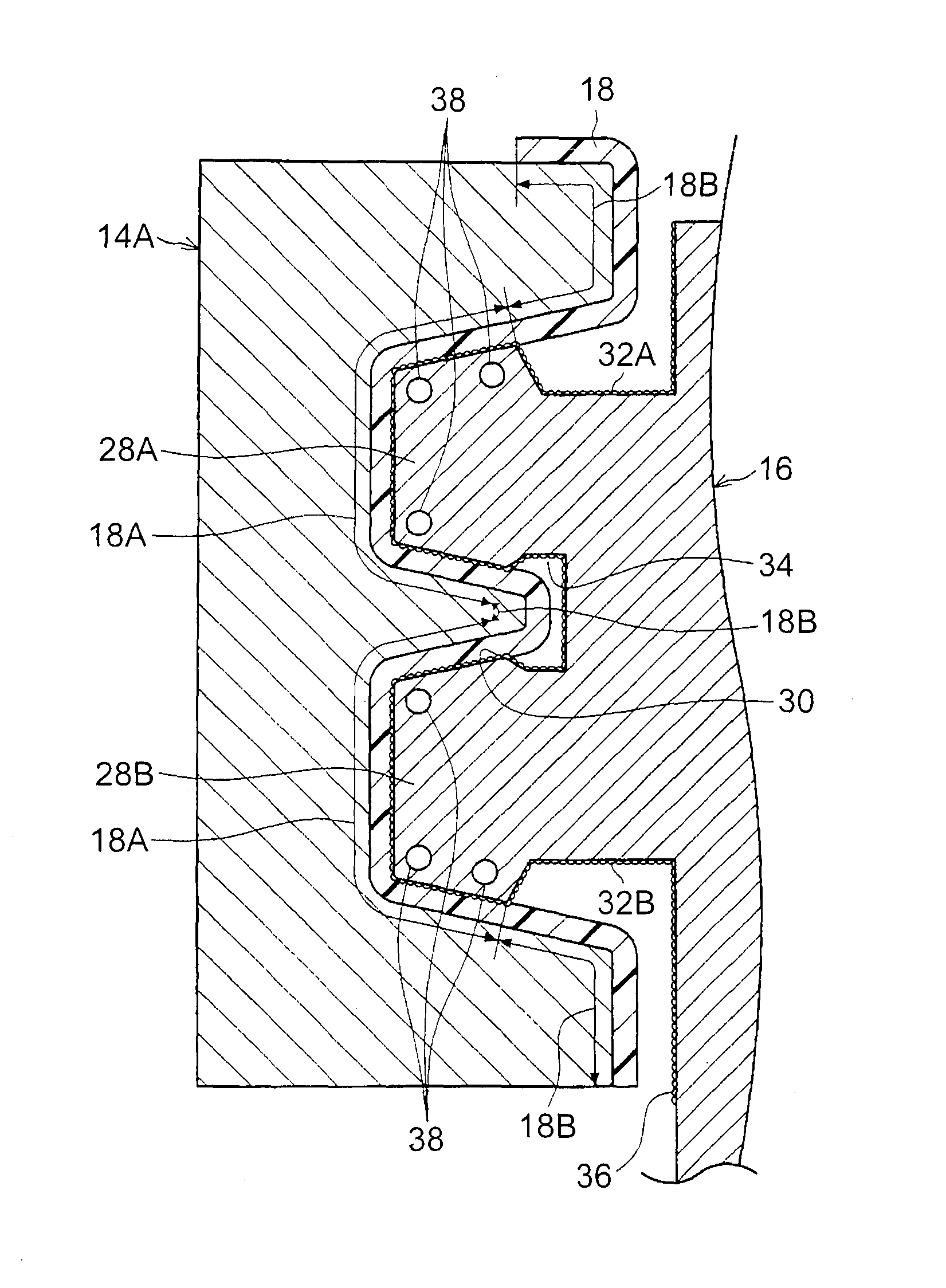
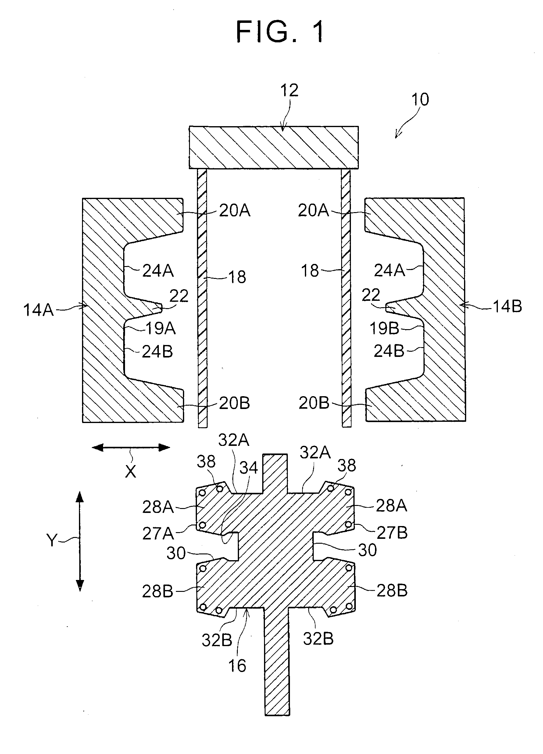
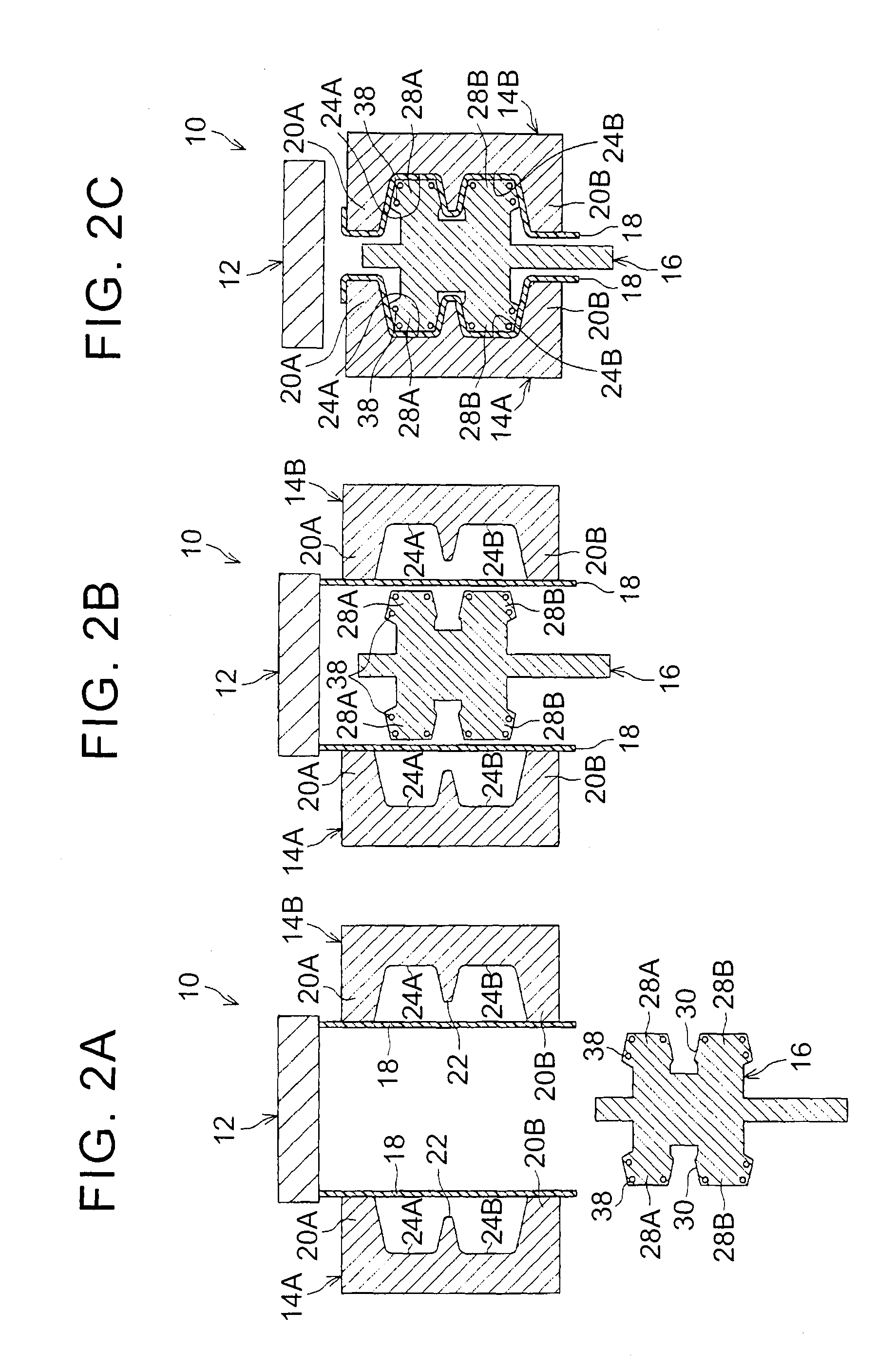
[0036]A description will be made on a method of manufacturing a resin molded product and a manufacturing device thereof according to one embodiment of the present invention with reference to FIG. 1 to FIG. 5. In FIG. 4 and FIG. 5, some portions are shown in an exaggerated manner for convenience of the description.

[0037]In this embodiment, a description will be made on a case of a fuel tank for a vehicle, the fuel tank being made of a resin (hereinafter referred to as a “resin fuel tank”) as an example of the resin molded product. First, a manufacturing device of the resin fuel tank will be described. Then, a method of manufacturing thereof will be described.

[0038]As shown in FIG. 1, a manufacturing device of the resin fuel tank (hereinafter referred to as a “manufacturing device”) 10 includes: a die head 12 that extrudes a sheet-like molten resin; a pair of shaping molds 14A, 14B that shapes the sheet-like molten resin, which has been extruded from the die head 12; and a cooling mol...


PUM

PropertyMeasurementUnit
Temperatureaaaaaaaaaa
Thicknessaaaaaaaaaa
Shapeaaaaaaaaaa

Abstract

A manufacturing device of a resin fuel tank can efficiently cool molded bodies when a cooling mold is inserted on the inside of the sheet-like molded bodies and shaping molds are closed. Here, semispherical convex portions are tightly formed on a surface of the cooling mold, and a contact area of the convex portions with the molded body gradually decreases in a boundary region of the molded body in which transition from an contact portion, with which the cooling mold contacts, to a non-contact portion, with which the cooling mold does not contact, is made. Thus, a temperature gradient of the molded body is suppressed in the boundary region, and formation of a groove in the boundary region can be suppressed.

Description

BACKGROUND OF THE INVENTION[0001]1. Field of the Invention[0002]The present invention relates to a method of manufacturing a resin molded product and a manufacturing device thereof.[0003]2. Description of Related Art[0004]It is disclosed that, in order to produce a large-sized hollow resin molded product by hollow molding, a three-dimensional cooling mold is inserted in a molten resin, which is extruded from an extrusion die, shaping molds are closed, and the molten resin is thereby cooled by both of the shaping molds and the cooling mold (see Japanese Patent Application Publication No. 2012-218212 (JP 2012-218212 A), for example). This can shorten a cooling time and thus to shorten a molding cycle.[0005]When the inside of the molten resin is cooled by the cooling mold, just as described, a groove may be formed by a difference in an amount of thermal contraction caused by a temperature difference in a boundary region between an contact portion of the resin mold that contacts the coo...

Claims


Application Information

Patent Timeline
IPC IPC(8): B29C51/42B29C51/08B29C51/30B29C47/00B29C48/07
CPCB29C47/0019B29C47/0054B29L2031/7172B29C49/04B29C51/082B29C2049/047B29C51/30B29C51/428B29C2049/021B29C2049/023B29C51/267B29C48/0017B29C48/07B29C49/04104B29C2949/08
Inventor ANZAWA, TAKAFUMISUZUKI, TEPPEI
Owner TOYOTA JIDOSHA KK
Learn More