
Multi-tenant monitoring

a multi-tenant and monitoring technology, applied in the field of multi-tenant computing, can solve the problems of unable to passivate a single tenant when that tenant becomes a tenant, the technology of wake-on-lan has ceased to be relevant, and the power consumption of a small amount of standby power

Active Publication Date: 2016-08-18
WARATEK LTD
View PDF4 Cites 18 Cited by
  • Summary
  • Abstract
  • Description
  • Claims
  • Application Information

AI Technical Summary

Benefits of technology

The present invention relates to a method and system for saving computer resources in a multi-tenanted computer environment. The technical effect of this invention is that it allows for efficient use of computer resources by monitoring the operations of each tenant and automatically inactivating or reactivating them based on predetermined characteristics. This approach helps to optimize the use of computer resources and improve overall efficiency in a multi-tenanted computer environment.

Problems solved by technology

This consumes a small amount of standby power, which is much less than normal operating power.
While wake-on-LAN has found success in server environments in that kind of role, with the advent of virtualization and cloud computing trends of the last 10 years, the wake-on-LAN technology has ceased to be relevant.
Specifically in multi-tenant cloud computing, where multiple independent and isolated applications are co-located on a single operating system, wake-on-LAN cannot be used to passivate a single tenant when that tenant becomes idle.
Idle tenants or applications in these multi-tenant cloud computing environments thus represent wasted computational capacity (such as wasted CPU reservations, wasted memory capacity, wasted I / O bandwidth, etc), because any computational capacity reserved for idle tenants / applications is by definition not available for use by other active tenants / applications.
This idle computational capacity could therefore potentially be more profitably redirected to other active or busy tenants or applications, thereby reducing the overall quantity of computing capacity required by shared computer system(s) to operate plural tenants.

Method used


Image

  • Multi-tenant monitoring
  • Multi-tenant monitoring
  • Multi-tenant monitoring

Examples


Embodiment Construction

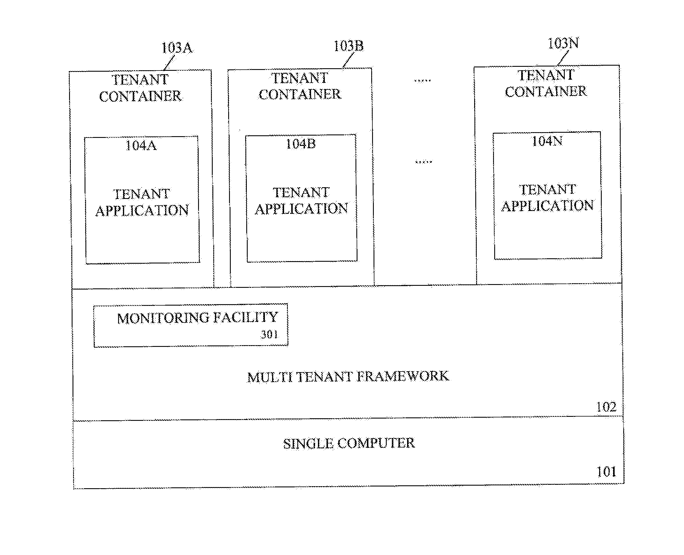
[0035]The preferred embodiment of the present invention discloses an alternative arrangement to wake-on-LAN which is designed specifically for multi-tenant cloud computing and virtualized server environments. This new arrangement identifies which tenants or applications of a multi-tenant server are idle, and when a tenant or application is identified as idle, it transparently reduces the reserved computational capacity footprint of the application or tenant without shutting down the tenancy or exiting the application. Furthermore, the near-instantaneous resumption of the idle tenant or application is achieved when some external event is detected which relates to the passivated tenant or application.

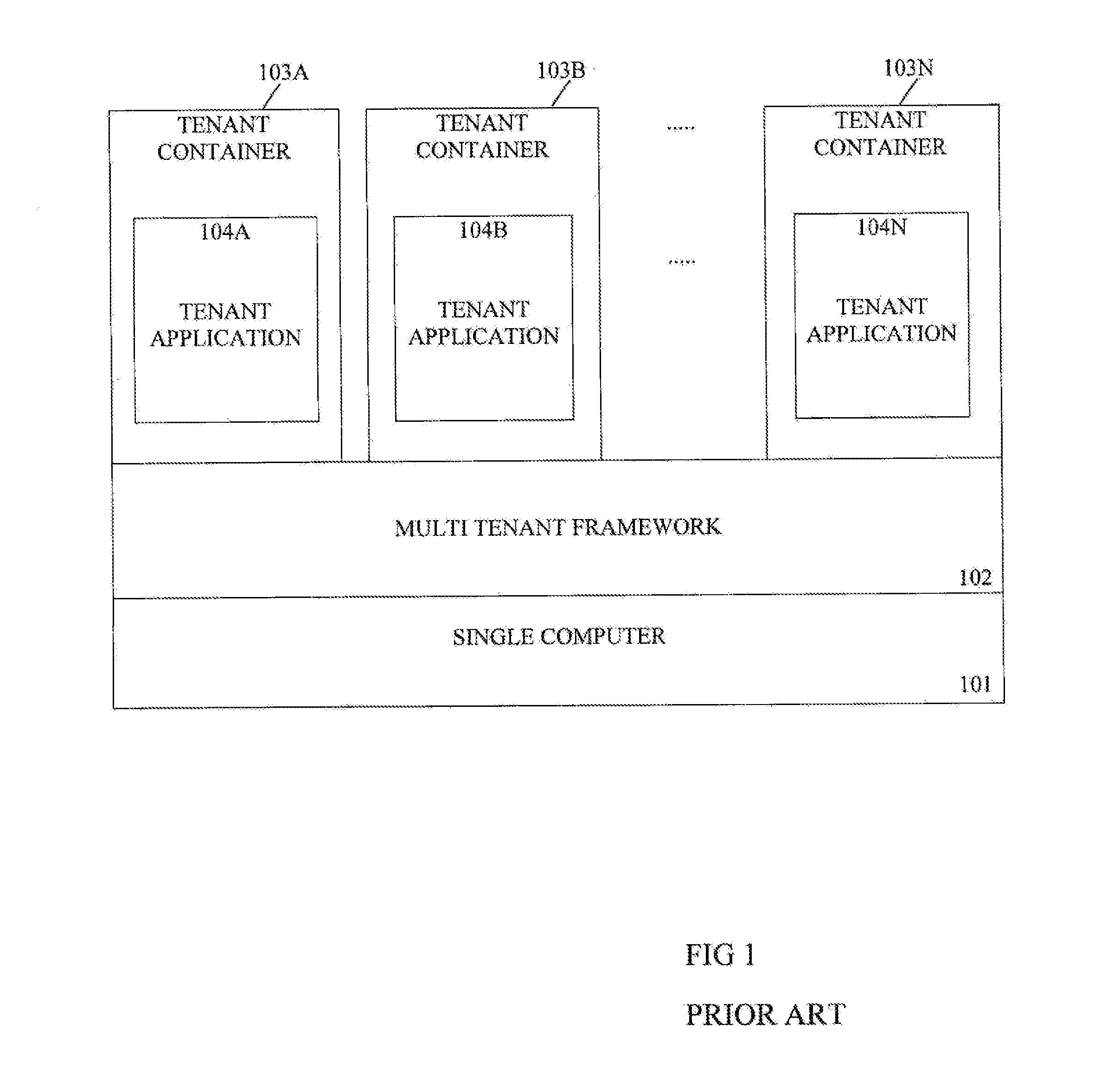
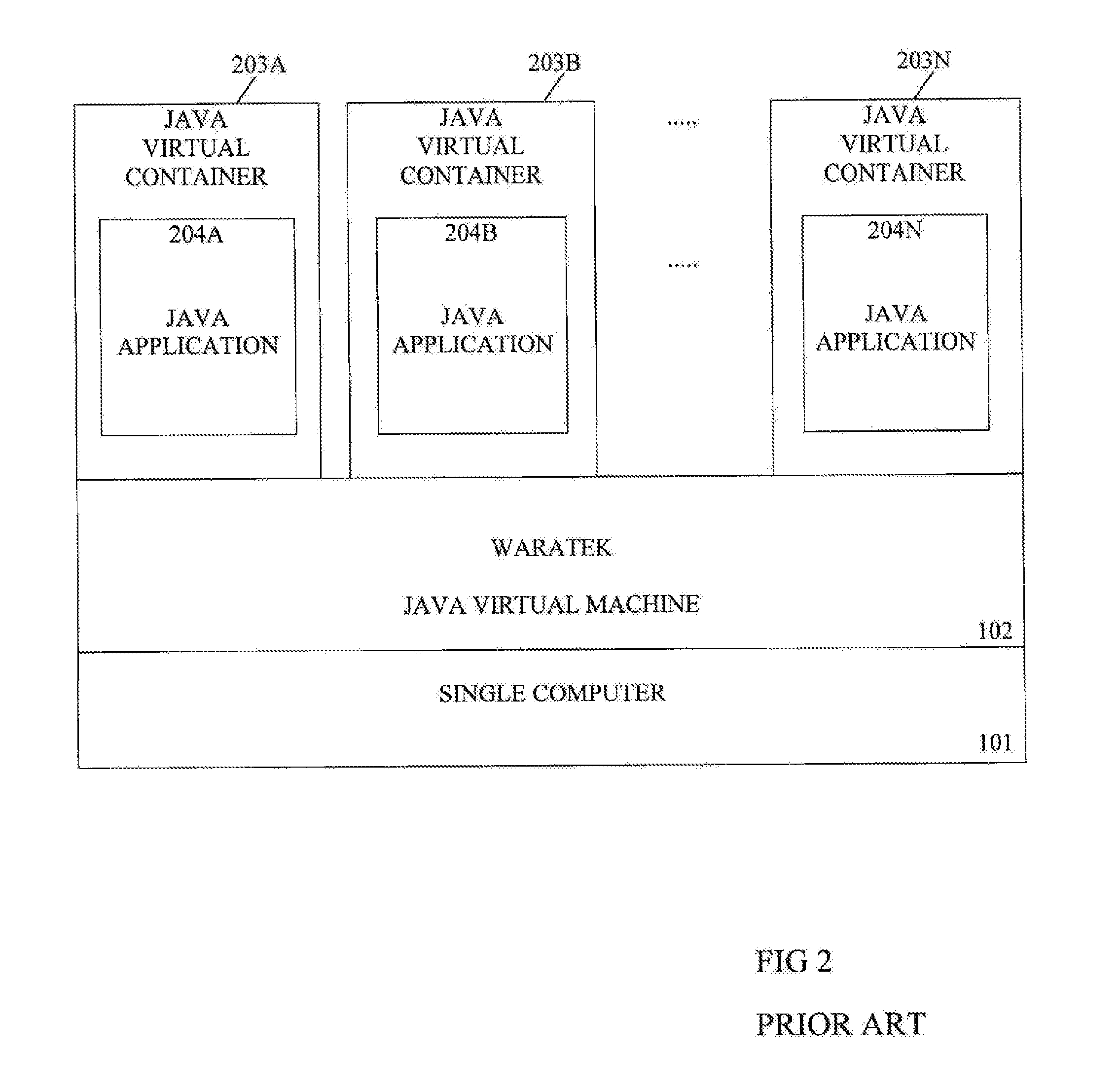
[0036]A prior art multi-tenant computer system comprising a single server computer is shown in FIG. 1. This multi-tenant computer system is operated with one of several multi-tenant frameworks 102 such as but not limited to a hypervisor, virtual machine monitor, operating system container...


PUM


Abstract

The present invention discloses an alternative arrangement to wake-on-LAN and which is designed specifically for multi-tenant cloud computing and virtualized server environments. This new arrangement identifies which tenants or applications of a multi-tenant server are idle, and when a tenant or application is identified as idle, it transparently reduces the reserved computational capacity footprint of the application or tenant without shutting down the tenancy or exiting the application. Furthermore, the near-instantaneous resumption of the idle tenant or application is achieved when some external event is detected which relates to the passivated tenant or application.

Description

FIELD OF THE INVENTION[0001]The present invention relates to multi-tenanted computing such as occurs in a cloud computing environment and / or in virtualisation environments.[0002]Various frameworks are known in which multi-tenanted computing can arise and these include hypervisor, virtual machine monitor, operating system containers, and multiple independent processes (or operating system tasks) on a shared operating system.[0003]The present invention is particularly concerned with reducing the consumption of the host's or “landlord's” computer assets by the multiple tenants. Such computer assets include memory, CPU user time power consumption, and input / output (I / O) bandwidth.BACKGROUND OF THE INVENTION[0004]Wake-on-LAN (WOL) is an Ethernet computer networking standard that allows a computer to be turned on or awakened by a network message.[0005]The message is usually sent by a program executed on another computer on the same local area network. It is also possible to initiate the m...

Claims


Application Information

Patent Timeline
Patent Type & Authority Applications(United States)
IPC IPC(8): G06F9/50G06F12/02G06F9/455
CPCG06F9/485G06F9/5022G06F9/45533G06F2009/45575G06F2212/702G06F9/5011G06F12/0253G06F2009/4557G06F2009/45583G06F9/45558
Inventor HOLT, JOHN MATTHEW
Owner WARATEK LTD
Learn More