
Apparatus including optical deflector controlled by saw-tooth voltage and its controlling method

a technology of optical deflector and control method, which is applied in the direction of optics, instruments, static indicating devices, etc., can solve the problems of difficult to accurately control the vertical increase manufacturing costs, and difficult to accurately control the projected view field, so as to achieve the effect of accurately controlling the deflection of the mirror

Inactive Publication Date: 2016-08-18
STANLEY ELECTRIC CO LTD
View PDF1 Cites 3 Cited by
  • Summary
  • Abstract
  • Description
  • Claims
  • Application Information

AI Technical Summary

Benefits of technology

The patent aims to solve the problem of DC offset voltage in a piezoelectric sensor. This problem can cause deflection of a mirror and affect the accuracy of control. The patent proposes a solution by using an integral voltage that includes the sense voltage and the DC offset characteristic voltage to compensate for the DC offset voltage. This allows for more accurate control of the mirror's deflection.

Problems solved by technology

In the above-described prior art video projection apparatus, however, since the sensor is susceptible to the fluctuation of a DC offset generated in the sense voltage thereof, it is difficult to accurately control the vertical deflection of the mirror.
Also, if a circuit is added to exclude the above-mentioned fluctuation of a DC offset, the manufacturing cost would be increased.
As a result, if the apparatus is a video projection apparatus, it is difficult to accurately control a projected view field.
Also, the fluctuation of a DC offset would be caused by charges stored in the piezoelectric sensor when it is operated for a long time.

Method used


Image

  • Apparatus including optical deflector controlled by saw-tooth voltage and its controlling method
  • Apparatus including optical deflector controlled by saw-tooth voltage and its controlling method
  • Apparatus including optical deflector controlled by saw-tooth voltage and its controlling method

Examples


Embodiment Construction

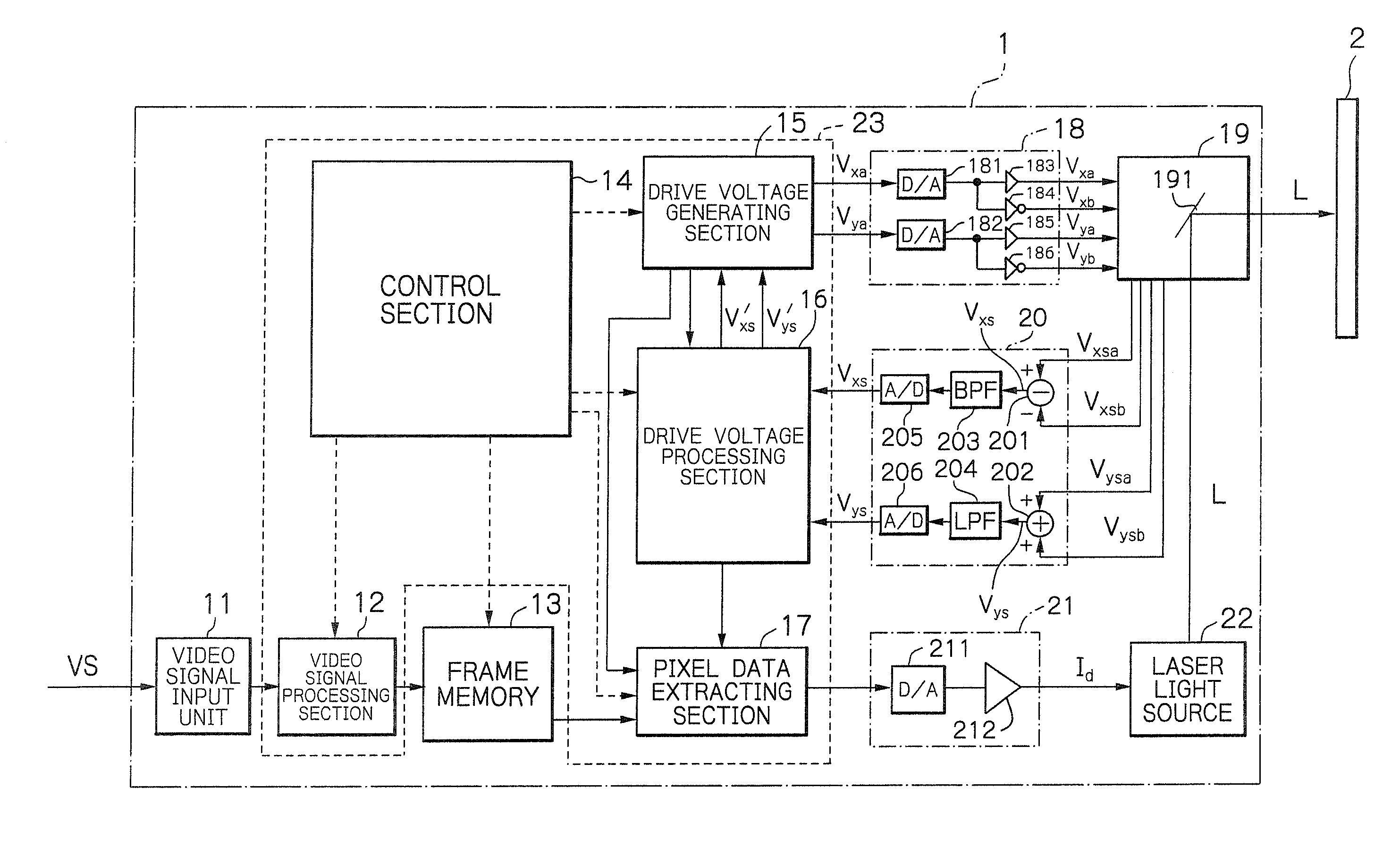
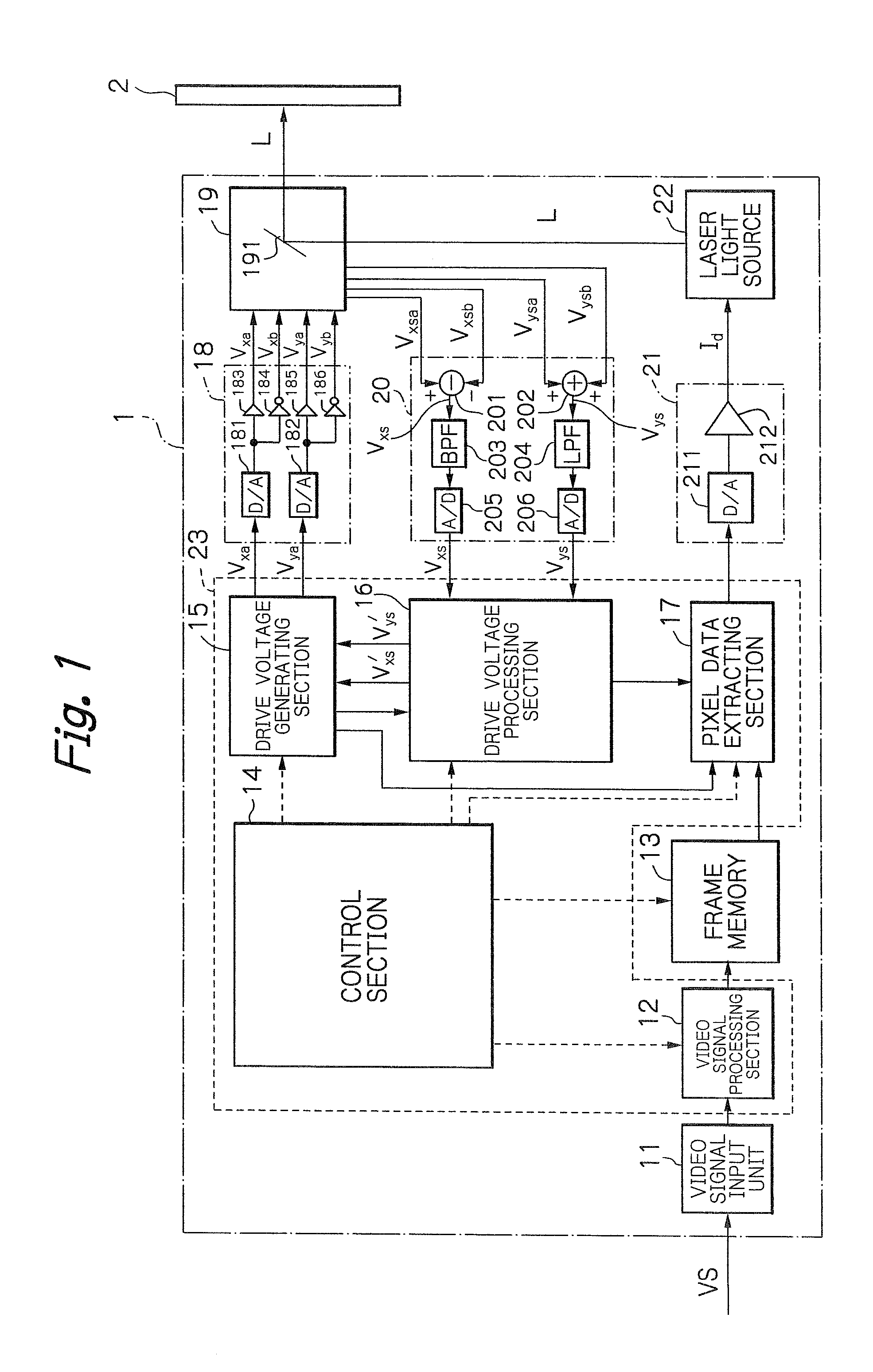
[0026]In FIG. 1, which illustrates an embodiment of the apparatus according to the presently disclosed subject matter, a video projection apparatus 1 receives a video signal VS from a video source such as a personal computer or a camera system to generate a laser beam L for a screen 2.

[0027]The video projection apparatus 1 is constructed by a video signal input unit 11, a video signal processing section 12, a frame memory 13 and a control section 14 for controlling the video signal processing section 12 and the frame memory 13.

[0028]The video signal input unit 11 is an analog red / green / blue (RGB) receiver or a digital video signal receiver such as a digital video interface (DVI), or a high-definition multimedia interface (HDMI). Video signals received by the video signal input unit 11 are processed by a video signal processing section 12 and are stored in the frame memory 13 frame by frame. For example, 60 frames per second are stored in the frame memory 13. The frame memory 13 is f...


PUM


Abstract

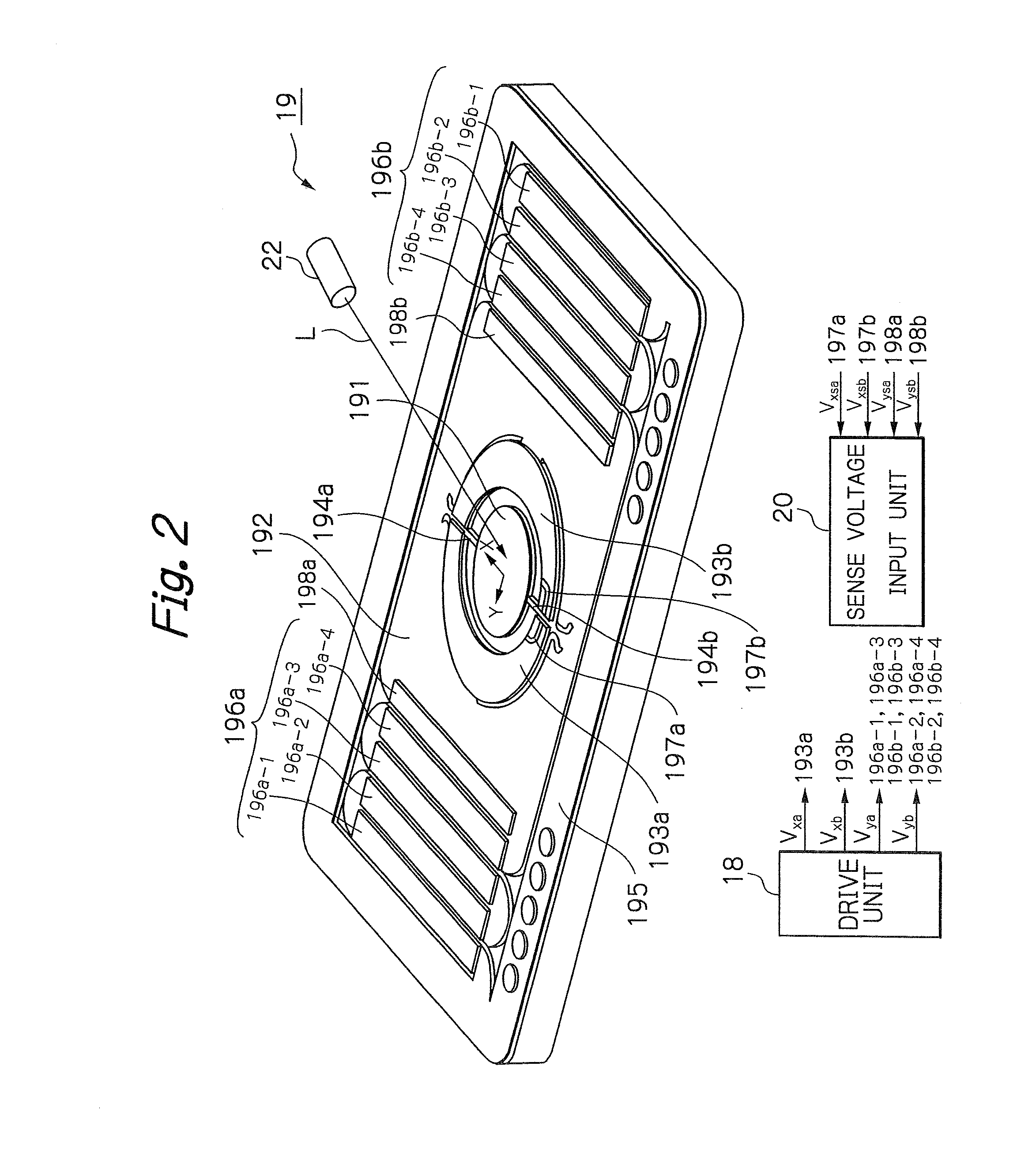
An optical deflector includes a mirror; a piezoelectric actuator adapted to rock the mirror around an axis of the mirror; and a piezoelectric sensor adapted to sense vibrations of the piezoelectric actuator. A control unit includes: a saw-tooth voltage generating block adapted to generate a saw-tooth voltage; an integral block adapted to calculate an integral voltage of a sum of a sense voltage of the piezoelectric sensor and a DC offset characteristic voltage; a DC offset characteristic voltage calculating block adapted to calculate the DC offset characteristic voltage in accordance with the integral voltage; a subtracter block adapted to generate a deviation between the saw-tooth voltage and the integral voltage; and a controller adapted to generate a drive voltage in accordance with the deviation to apply the drive voltage to the piezoelectric actuator.

Description

[0001]This application claims the priority benefit under 35 U. S. C. §119 to Japanese Patent Application No. JP2015-025221 filed on Feb. 12, 2015, which disclosure is hereby incorporated in its entirety by reference.BACKGROUND[0002]1. Field[0003]The presently disclosed subject matter relates to an apparatus including an optical deflector controlled by a saw-tooth voltage and its controlling method, and more specifically, to a video projection apparatus and its controlling method. The video projection apparatus can be used as a pico projector, a head mount display (HMD) unit, a head up display (HUD) unit and the like.[0004]2. Description of the Related Art[0005]A prior art video projection apparatus is constructed by a two-dimensional optical deflector as an optical scanner manufactured by a micro electro mechanical system (MEMS) device manufactured using a semiconductor process and micro machine technology (see: JP5543468B2 & US2010 / 0073748A1). Since the MEMS optical scanner is focu...

Claims


Application Information

Patent Timeline
Patent Type & Authority Applications(United States)
IPC IPC(8): G02B26/08G02B26/10
CPCG02B26/0858G02B26/105G09G3/00G09G3/025
Inventor SAITO
Owner STANLEY ELECTRIC CO LTD
Learn More