
Systems, devices and methods for gas distribution in a sorber

a technology of sorber and gas distribution, which is applied in the direction of sorber, refrigeration machine, lighting and heating apparatus, etc., can solve the problems of ceramic distributors that cannot be easily damaged, ceramic distributors that have difficulty with vibration, and cloth distributors that have also been found to have some downsides

Active Publication Date: 2016-08-18
ROCKY RES
View PDF3 Cites 10 Cited by
  • Summary
  • Abstract
  • Description
  • Claims
  • Application Information

AI Technical Summary

Benefits of technology

The patent describes an adsorption chilling system that uses a rigid gas distribution tube with a porous sidewall to distribute gas to a sorbent. The system has several aspects that provide advantages over existing systems. The technical effects of this system include improved gas distribution, reduced pressure drop, and improved heat transfer. The system can be used in complex compound reactors and can be designed to operate in different phases. The method of distributing gas to the sorbent involves flowing the gas through the channel of the rigid gas distribution tube and permeating at least a portion of the porous sidewall with the gas while adsorbing it onto the sorbent. The desorbed gas can also be flowed through the channel of the tube.

Problems solved by technology

However, the ceramic distributors are fragile and can fracture easily, especially in non-stationary or vibratory environments.
For example, ceramic distributors can have difficulty withstanding the vibrations caused by transportation in rough terrain.
Cloth distributors have also been found to have some downsides, particularly due to their propensity to clog after multiple cycles.
This clogging can increase the pressure drop of the refrigerant in the systems and thereby reduce the performance of the sorber and the absorption system.

Method used


Image

  • Systems, devices and methods for gas distribution in a sorber
  • Systems, devices and methods for gas distribution in a sorber
  • Systems, devices and methods for gas distribution in a sorber

Examples


Embodiment Construction

,” one will understand how the features of the embodiments described herein provide advantages over existing systems, devices and methods for distributing gas in complex compound reactors.

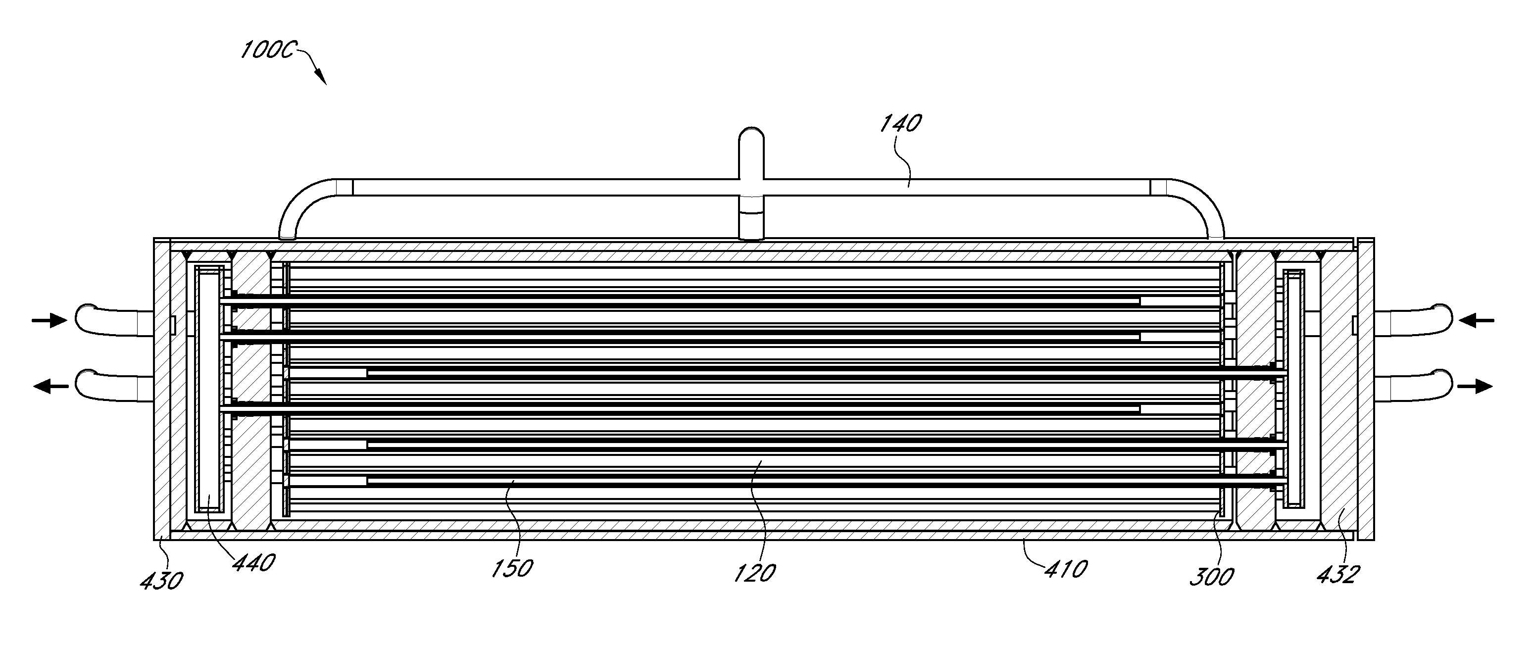
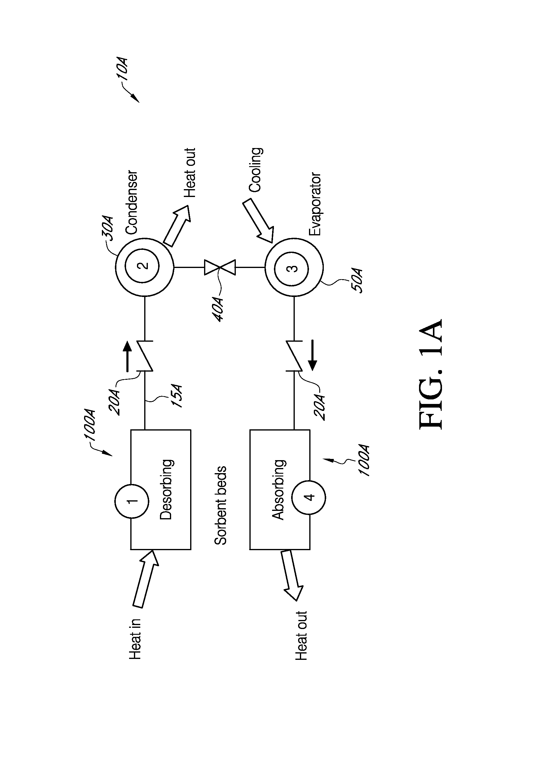
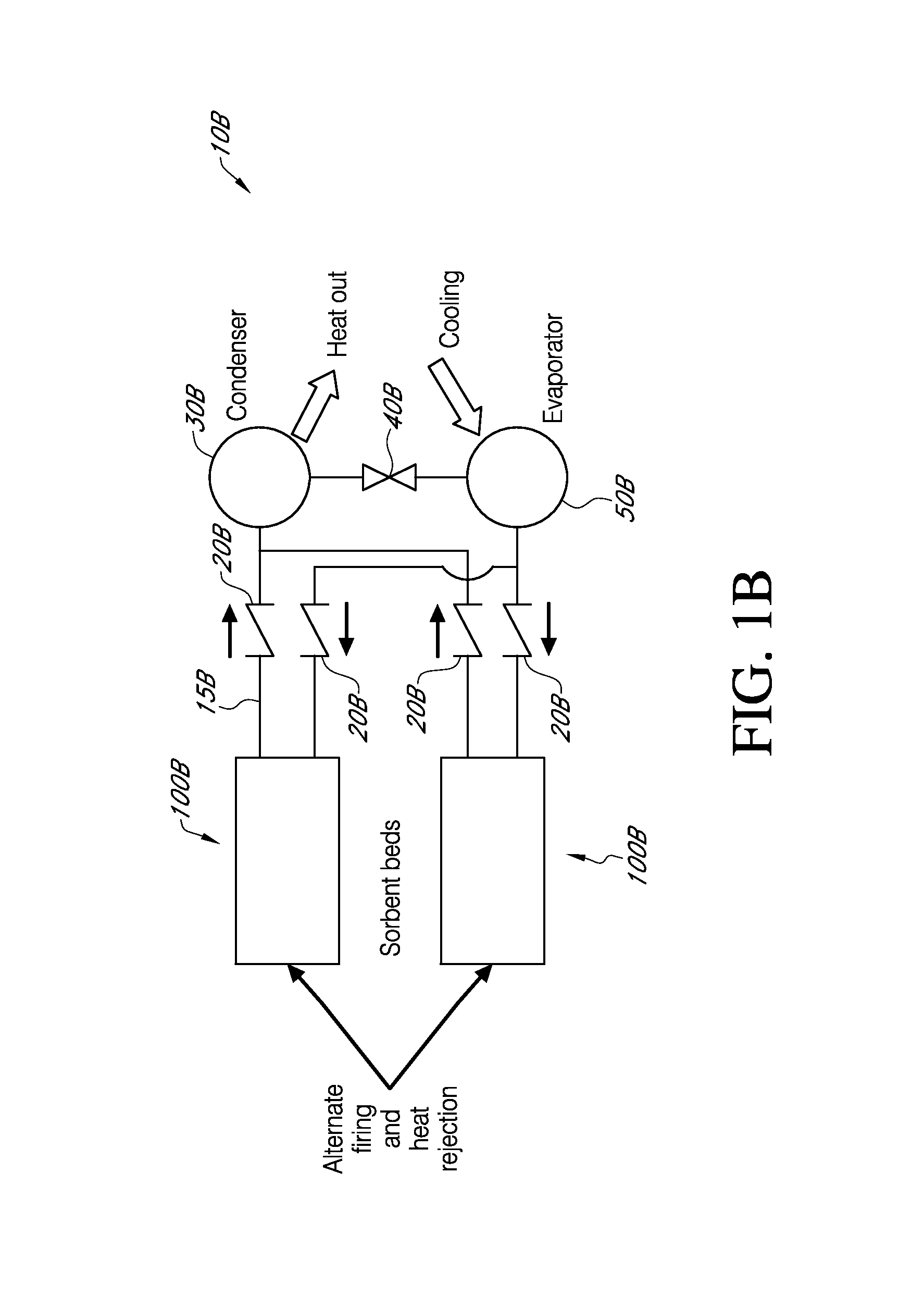
[0008]In one aspect, an adsorption chilling system is disclosed. The system comprises a first sorber comprising a sorbent configured to adsorb a gas thereon and a rigid gas distribution tube coupled with the first sorber and comprising a porous sidewall defining a channel therein. The tube is configured to allow passage of the gas from an interior of the channel through the porous sidewall and to the sorbent outside the channel.

[0009]In some embodiments, the rigid gas distribution tube comprises an elongated matrix defining the porous sidewall, a reinforcement contained in the matrix to form a rigid composite, and a plurality of pores defined by the rigid composite and configured to allow the passage of the gas. The matrix may be an epoxy and the reinforcement may be fiber glass. In some embodiment...


PUM


Abstract

Features for distributing a sorber gas in cooling, heating or refrigeration systems with sorbers are disclosed. The sorbers may adsorb gas onto a sorbent material and desorb gas therefrom. Distribution of the gas to and from the sorber may be done with porous, rigid tubes. The tubes may be formed of composite material having pores. The pores may be implemented by flowing fluids through the composite material while the material cures. The sorbers may be reinforced with rods to provide greater strength and stability in load-inducing environments. The tubes may extend through the sorbent and thereby provide a channel for the gas to flow to and from the sorbent and the rest of the cooling, heating or refrigeration system.

Description

BACKGROUND[0001]1. Field of the Invention[0002]This disclosure relates generally to sorption refrigeration systems using sorbers and with complex compounds and a sorber gas. In particular, features for distributing the sorber gas in such systems are disclosed.[0003]2. Description of the Related Art[0004]Adsorption / desorption or also referred to as absorption / desorption reactions between polar gases and certain metal salts yield complex compounds which are the basis for efficient refrigeration, thermal storage, heat pump systems and power systems having high energy density. However, energy density, a measure of the quantity of polar gas adsorbed on the salt, which translates into the amount of work or energy which can be stored in a given amount of the complex compound, is only one parameter to be considered in designing commercially attractive systems.[0005]Of significance, if not greater importance, are the reaction rates between the gas and the complex compound, which result in th...

Claims


Application Information

Patent Timeline
Patent Type & Authority Applications(United States)
IPC IPC(8): F25B17/08
CPCF25B17/08F25B37/00Y02A30/27Y02B30/00F25B17/083
Inventor ROCKENFELLER, UWEKHALILI, KAVEH
Owner ROCKY RES
Learn More