
Variable playback speed template for video editing application

a video editing and variable playback speed technology, applied in the field of camera systems, can solve the problems of increasing video management difficulty, consuming a lot of resources, and manually searching through raw videos (“scrubbing”) to identify the best scenes,

Active Publication Date: 2016-08-04
GOPRO
View PDF2 Cites 141 Cited by
  • Summary
  • Abstract
  • Description
  • Claims
  • Application Information

AI Technical Summary

Benefits of technology

The patent text describes a system that allows users to easily apply playback speed effects to videos. The system identifies a portion of the video and selects a speed ramp template for that portion, without user intervention. The system can also make use of highlight tags in the video to align the playback speed template with relevant video portions. The speed ramp templates can be flexible and have scalable playback speed ratios, making it easier for users to create and edit videos with different playback speeds. The technical effect of the patent is to simplify the process of applying playback speed effects to videos, making them easier for users to edit and share.

Problems solved by technology

However, as users capture increasingly more and longer videos, video management becomes increasingly difficult.
Manually searching through raw videos (“scrubbing”) to identify the best scenes is extremely time consuming.
Automated video processing to identify the best scenes can be very resource-intensive, particularly with high-resolution, raw-format video data.
Even when a best scene is identified, modifying a scene can be a labor-intensive process.
However, a sudden change from normal playback speed to slow-motion playback results in an unpolished video with a less professional feel.
However, specifying these different degrees of slow-motion effect over the course of the scene is a laborious process.

Method used


Image

  • Variable playback speed template for video editing application
  • Variable playback speed template for video editing application
  • Variable playback speed template for video editing application

Examples


example camera

Configuration

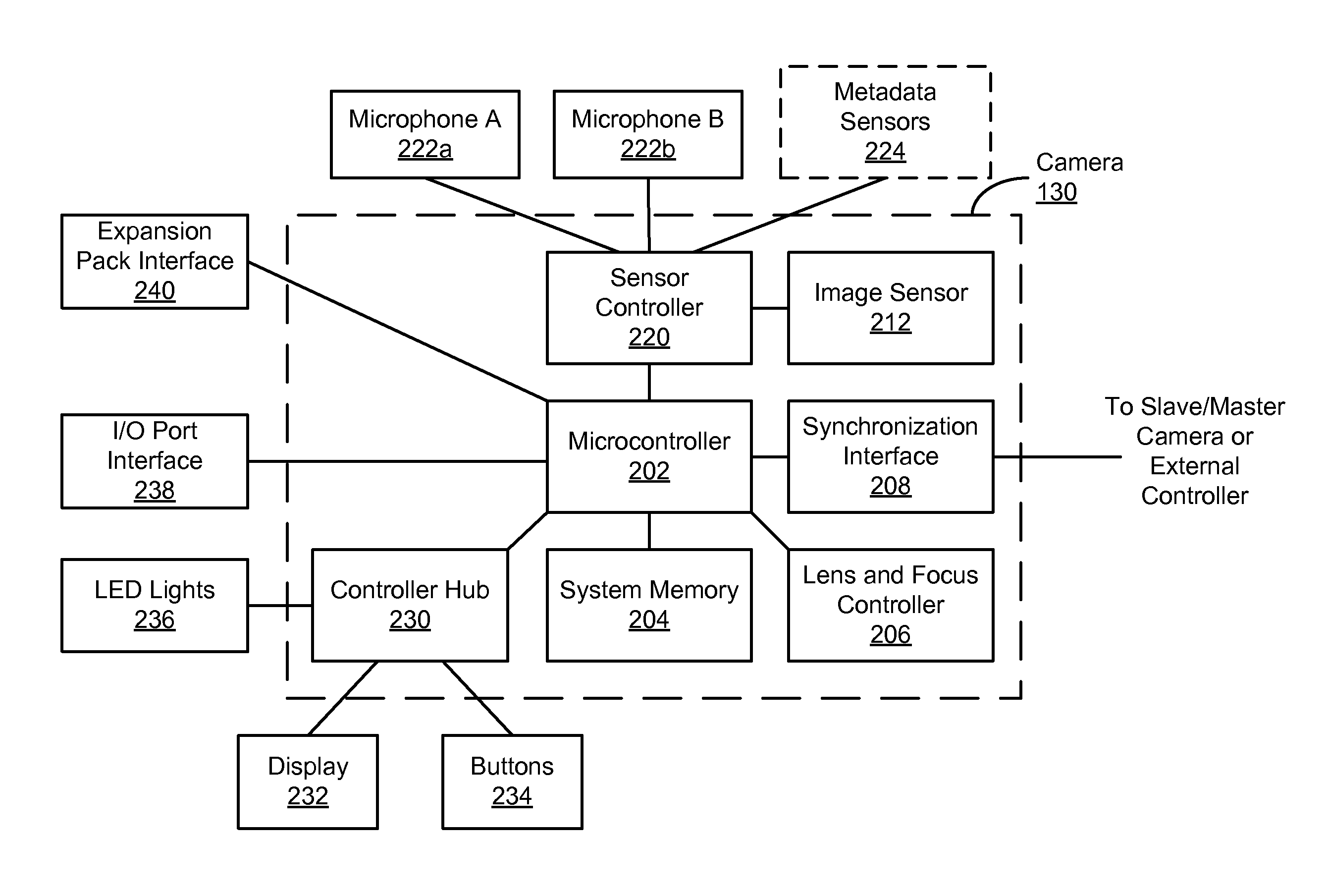
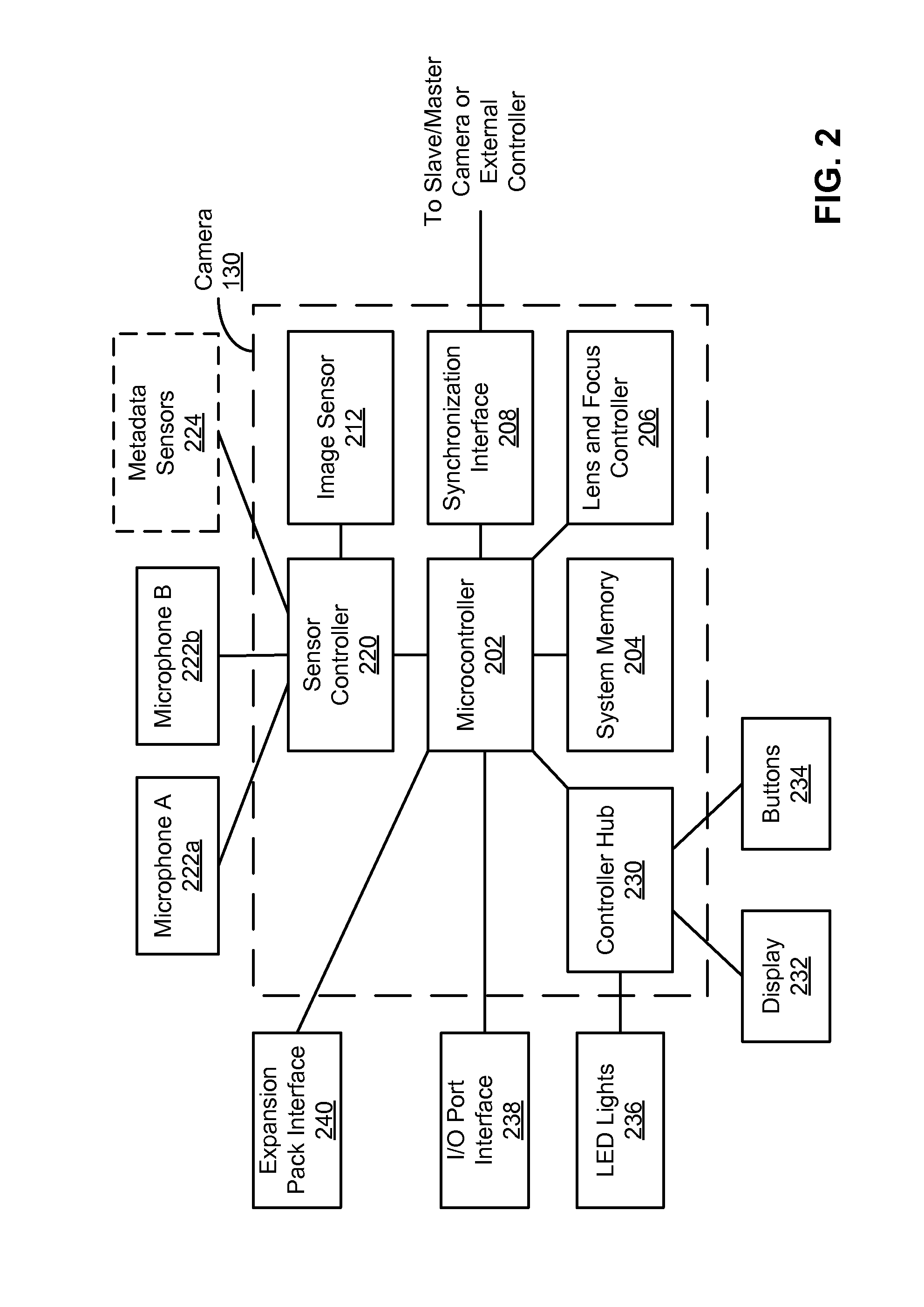
[0028]FIG. 2 is a block diagram illustrating a camera system, according to one embodiment. The camera 130 includes one or more microcontrollers 202 (such as one or more microprocessors or other processors) that control the operation and functionality of the camera 130. A lens and focus controller 206 is configured to control the operation and configuration of the camera lens. A system memory 204 is configured to store executable computer instructions that, when executed by the microcontroller 202, perform the camera functionalities described herein. A synchronization interface 208 is configured to synchronize the camera 130 with other cameras or with other external devices, such as a remote control, a second camera 130, a smartphone, a client device 135, or a video server 140.

[0029]A controller hub 230 transmits and receives information from various I / O components. In one embodiment, the controller hub 230 interfaces with LED lights 236, a display 232, buttons 234, micr...


PUM

PropertyMeasurementUnit
threshold of timeaaaaaaaaaa
timeaaaaaaaaaa
speedaaaaaaaaaa

Abstract

A playback speed effect is applied to a video using a playback speed template. The playback speed template specifies playback speed ratios (i.e., ratios between playback duration and capture duration) at the highlight moment, at a template start time, and at a template end time. A video associated with a highlight tag indicating a highlight capture time of a highlight moment within the video is accessed. An input portion of the video including the highlight moment is identified. The duration of the input portion has a duration depending on the template start time and the template end time. A playback speed template is applied to the input portion. A modified video including a modified video portion is generated from the input portion of the video according to the applied playback speed template and is provided for subsequent playback.

Description

BACKGROUND[0001]1. Technical Field[0002]This disclosure relates to a camera system, and more specifically, to processing video data captured using a camera system.[0003]2. Description of the Related Art[0004]Digital cameras are increasingly used to capture videos in a variety of settings, for instance outdoors or in a sports environment. However, as users capture increasingly more and longer videos, video management becomes increasingly difficult. Manually searching through raw videos (“scrubbing”) to identify the best scenes is extremely time consuming. Automated video processing to identify the best scenes can be very resource-intensive, particularly with high-resolution, raw-format video data. Even when a best scene is identified, modifying a scene can be a labor-intensive process. For example, to apply a slow-motion effect, a user selects a start time, an end time, and a degree of slow-motion effect. However, a sudden change from normal playback speed to slow-motion playback res...

Claims


Application Information

Patent Timeline
Patent Type & Authority Applications(United States)
IPC IPC(8): G11B27/00G11B27/022H04N5/765G06F17/30
CPCG11B27/005H04N5/765G11B27/022G06F17/30817H04N5/783H04N5/93H04N9/8205G11B27/031G11B27/28G06F16/739G06F16/78G11B27/19
Inventor MATIAS, JOVEN MICHAELSIEVERT, OTTO KENNETHBODINET, JOSHUA EDWARD
Owner GOPRO
Learn More