
Trigeneration energy supply system

a technology of energy supply system and energy supply system, which is applied in the direction of machines/engines, lighting and heating apparatus, heating types, etc., can solve the problems of difficult to cope with cooling load, low efficiency of adsorption type (or absorption type) cooling system, and invariable generation amount of sunlight or wind power generation method, etc., to achieve efficient hot water utilization, increase energy efficiency and operability, and improve energy efficiency of trigeneration energy supply system

Active Publication Date: 2016-08-04
KOREA INST OF ENERGY RES
View PDF7 Cites 3 Cited by
  • Summary
  • Abstract
  • Description
  • Claims
  • Application Information

AI Technical Summary

Benefits of technology

The present invention provides a system that can efficiently cool and store power energy using a cooled refrigerant and water stored in the upper part of the system. This function allows for the appropriate provision of cooling when there is no coincidence between energy demand and supply. The system can also make efficient use of energy produced through cogeneration or new renewable sources, like sunlight or wind power, through the energy storage function. This increases the energy efficiency of the system and makes it more flexible for use.

Problems solved by technology

A problem of the conventional technology described above is that the adsorption type (or an absorption type) cooling system has a lower coefficient of performance (COP) than a turbo type cooling system.
Accordingly, since it is generally difficult to cope with cooling loads of a whole building only using an adsorption type (or an absorption type) refrigerator, the adsorption type (or the absorption type) refrigerator may be used in combination with a turbo type refrigerator.
However, a generation amount of sunlight or wind power generation method is not uniform but variable depending on weather, seasons, conditions, etc.
Due to intermittent generation which is a disadvantage of sunlight and wind power generation methods, since a point in time at which energy (power, heat, etc.) is generated using a new renewable energy source does not coincide with a point in time at which users demand energy, availability of such new renewable energy sources greatly decreases in the aspects of system operation and economy.

Method used


Image

  • Trigeneration energy supply system
  • Trigeneration energy supply system
  • Trigeneration energy supply system

Examples


Embodiment Construction

[0025]Since the present invention may have various modifications and several embodiments, exemplary embodiments thereof will be described in detail referring to the drawings. However, the present invention will not be limited to the exemplary embodiments but should be understood as including all modifications, equivalents, and substitutes included in the spirit and the technical scope of the present invention.

[0026]It will be understood that although the terms “first”, “second”, etc. may be used herein to describe various components, these components should not be limited by these terms. These terms are used merely to distinguish one element from another. For example, without departing from the scope of the present invention, a second component may be designated as a first component, and similarly, the first component may be designated as the second component. The term “and / or” includes any and all combinations or one of a plurality of associated listed items.

[0027]It will be unders...


PUM


Abstract

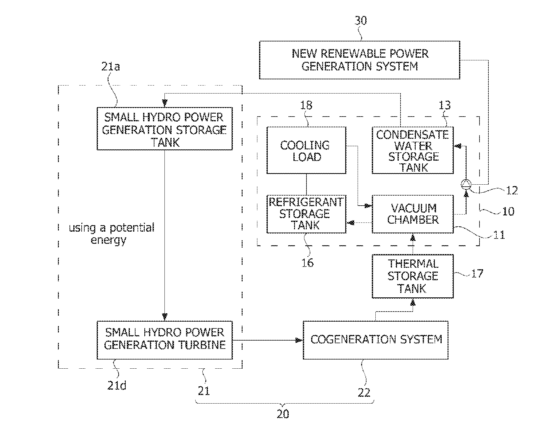
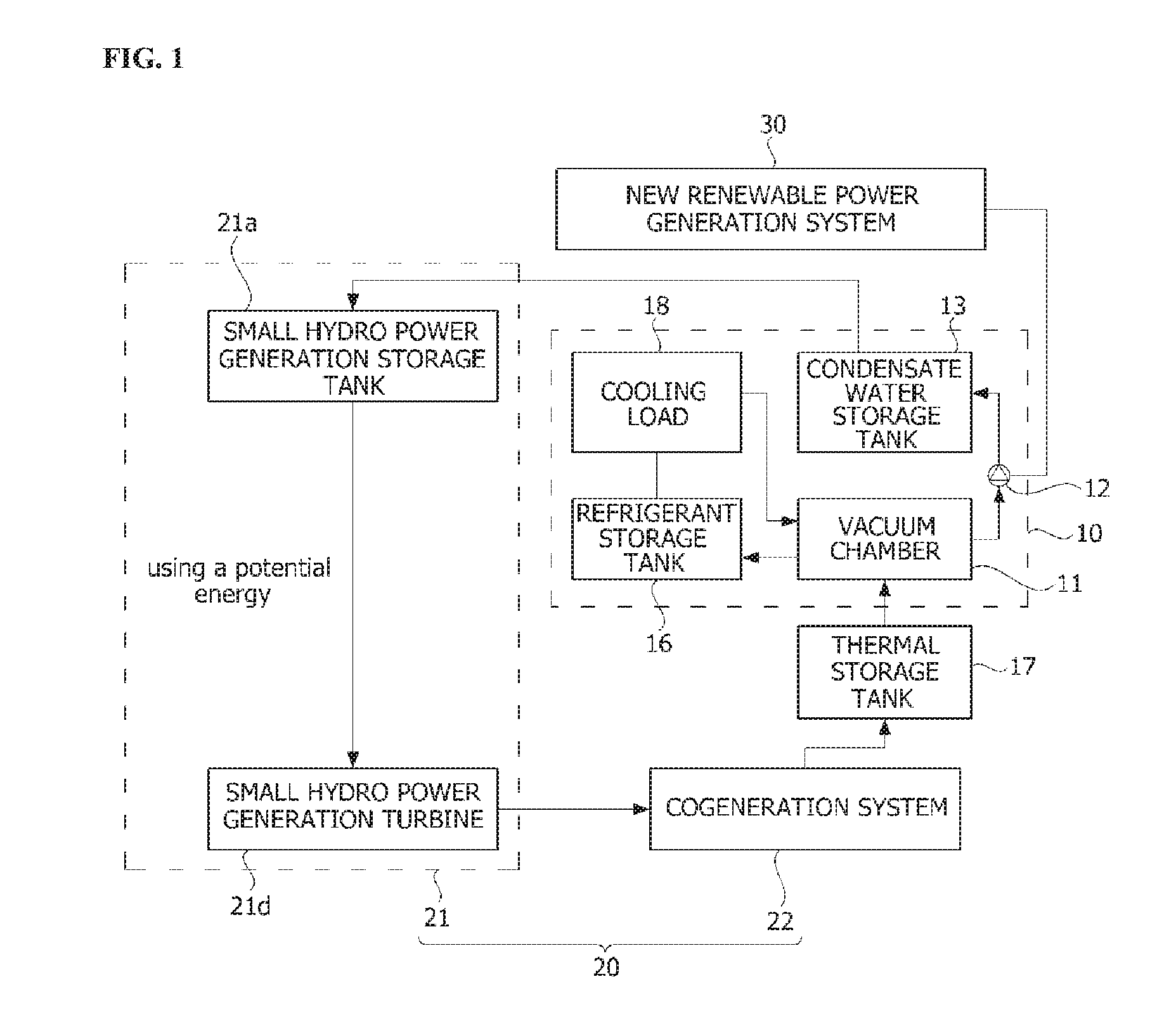
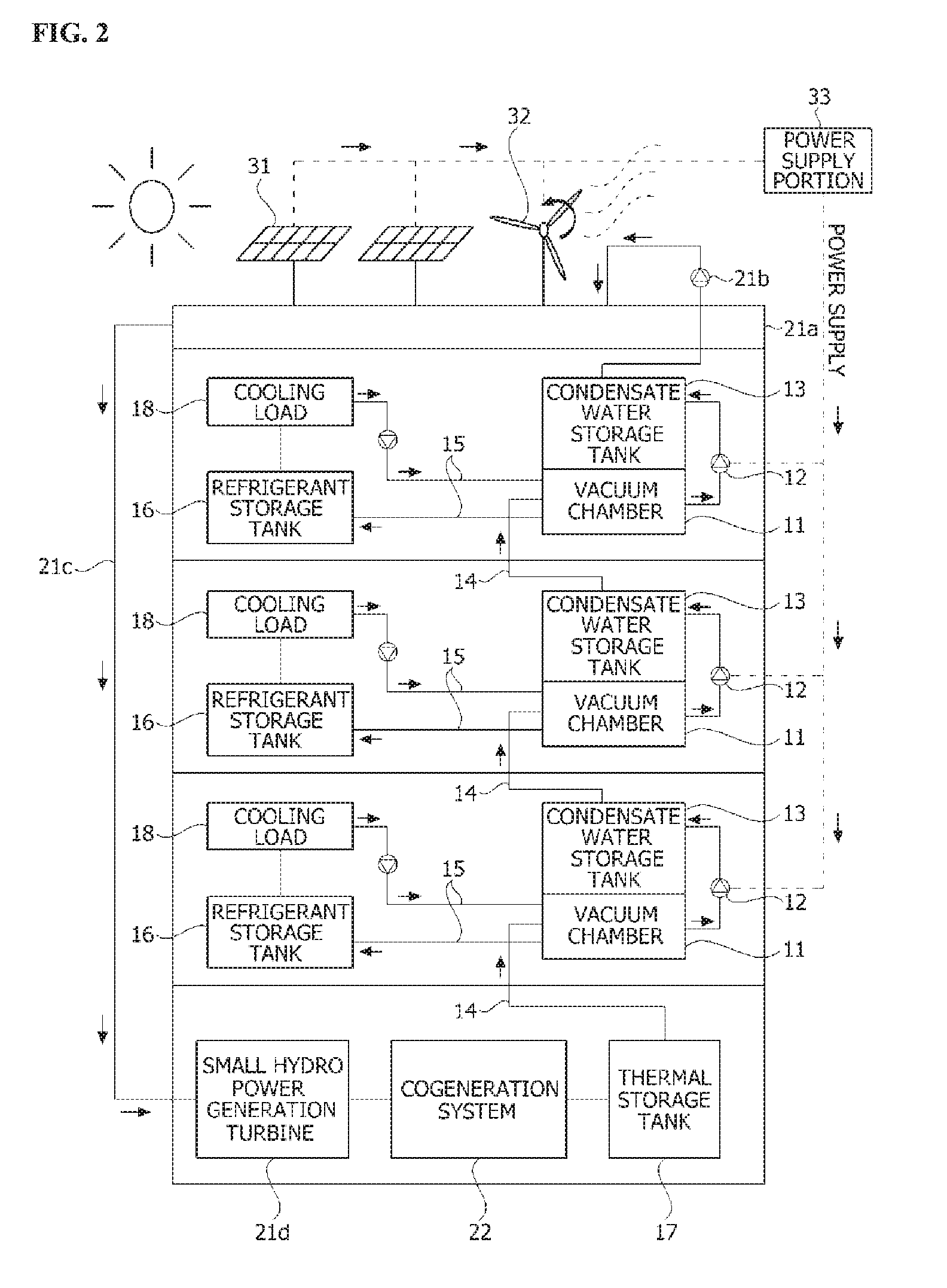
The present invention relates to a trigeneration energy supply system having improved cooling and system use efficiency. The trigeneration energy supply system according to one embodiment of the present invention can comprise: a vacuum pump; a vacuum chamber inside which a vacuum is created by the vacuum pump; a condensed water storage tank positioned higher than the vacuum chamber, and prepared so as to store condensed water formed when steam generated by evaporating water brought inside the vacuum chamber is transferred to the inside of the tank by the vacuum pump; a cooling pipeline arranged to pass through the inside of the vacuum chamber cooled during the water evaporation and prepared to deliver cool air to a cooling load; and a small hydroelectric power generation system for generating electrical power by allowing the condensed water stored in the condensed water storage tank to be poured from at least the height of the condensed water storage tank.

Description

TECHNICAL FIELD[0001]The present invention relates to a trigeneration energy supply system capable of providing all of power, heating, and cooling to a building.BACKGROUND ART[0002]Generally, a trigeneration energy supply system is a system which provides all of power, heating, and cooling to a building. A conventional trigeneration energy supply system, in addition to a cogeneration system, uses an absorption type refrigerator, an adsorption type refrigerator, a turbo type refrigerator, a dehumidification type refrigerator, etc. Generation and heating are performed at the same time using the cogeneration system, and cooling is performed by operating the absorption type refrigerator, the adsorption type refrigerator, the turbo type refrigerator, or the dehumidification type refrigerator using waste heat and surplus power generated by a cogeneration process. Particularly, since a demand for heating generally decreases and a demand for cooling greatly increases in summer, it is very i...

Claims


Application Information

Patent Timeline
Patent Type & Authority Applications(United States)
IPC IPC(8): F24D10/00F24F3/06F03B13/00F24D18/00
CPCF03B13/00F24D1/00F24D2200/26Y02E20/14F01K27/005F24D10/00F24F3/06F24H2240/02Y02P80/15Y02P80/14Y02B30/17F24D2101/20F24D2101/40F24D18/00F24D2101/10F24D2103/17F02G5/04F24D11/0221Y02B30/625
Inventor IM, YONG HOONLEE, JAE YONGLEE, DONG HYUN
Owner KOREA INST OF ENERGY RES
Learn More