
Shell structure and manufacturing method thereof

a shell structure and manufacturing method technology, applied in the direction of casings/cabinets/drawers, casings/cabinets/drawers details, electric apparatuses, etc., can solve the problem that the rigid casing can still be damaged, and achieve the effect of favorable crashworthiness

Active Publication Date: 2016-07-21
COMPAL ELECTRONICS INC
View PDF1 Cites 3 Cited by
  • Summary
  • Abstract
  • Description
  • Claims
  • Application Information

AI Technical Summary

Benefits of technology

The invention is a shell structure that is thin and smooth and has a good crashworthiness effect. It is made up of an elastic material structure and a fiber structure that provides both flexibility and tenacity. The buffering space between the casing and the frame is aligned to the border of the two sides of the casing, which is most likely to be impacted when dropped. This allows for sufficient elastic deformability to absorb the impact force. Overall, this design does not require additional elastic material or overlapping casings, which makes it compliant with the trend for thin and smooth devices.

Problems solved by technology

However, this type of design causes the structure at the corner region of the smart phone to be less smooth and affects an appearance thereof, and the rigid casing can still be damaged when subjected to an external force exceeding a limit bearable by the rigid casing.

Method used


Image

  • Shell structure and manufacturing method thereof
  • Shell structure and manufacturing method thereof
  • Shell structure and manufacturing method thereof

Examples


Embodiment Construction

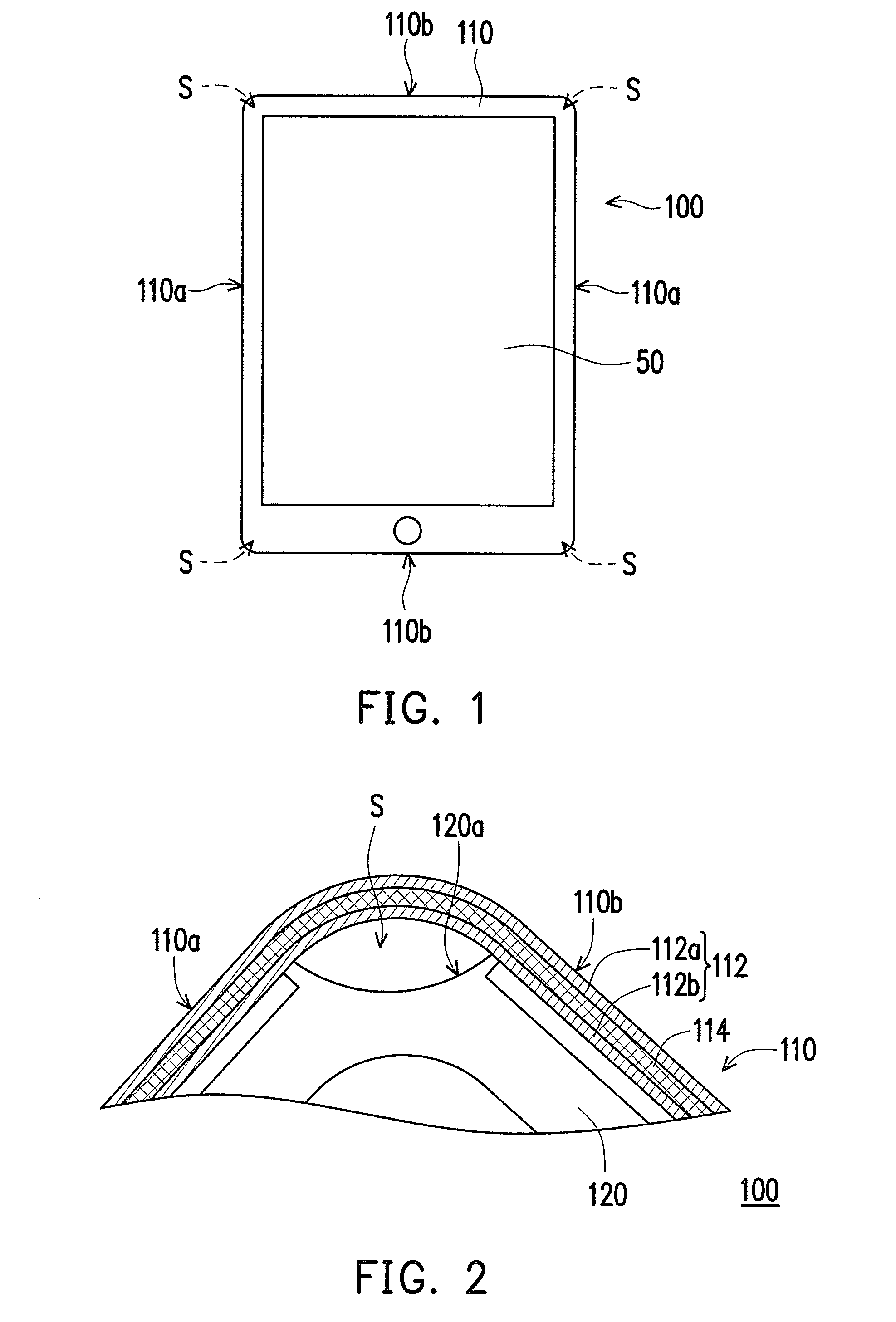
[0046]FIG. 1 illustrates a shell structure being applied to a handheld electronic device according to an embodiment of the invention. Referring to FIG. 1, a shell structure 100 of the present embodiment is, for example, a casing of the handheld electronic device (e.g., Smart phone), and the shell structure 100 is configured to accommodate internal components (e.g., motherboard and electronic components thereon) of the handheld electronic device and expose a touch display panel 50 of the handheld electronic device for a user to view and operate.

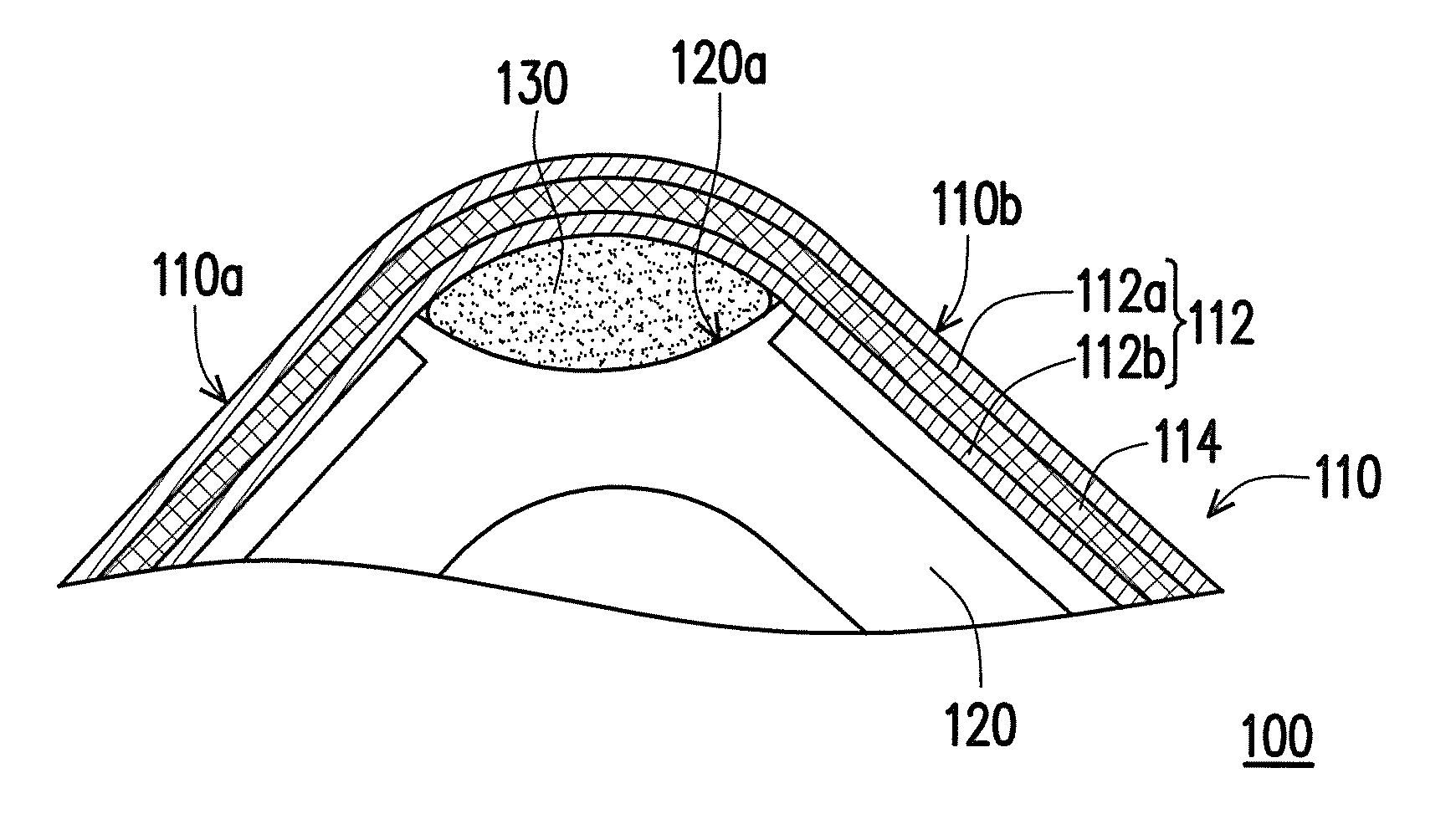
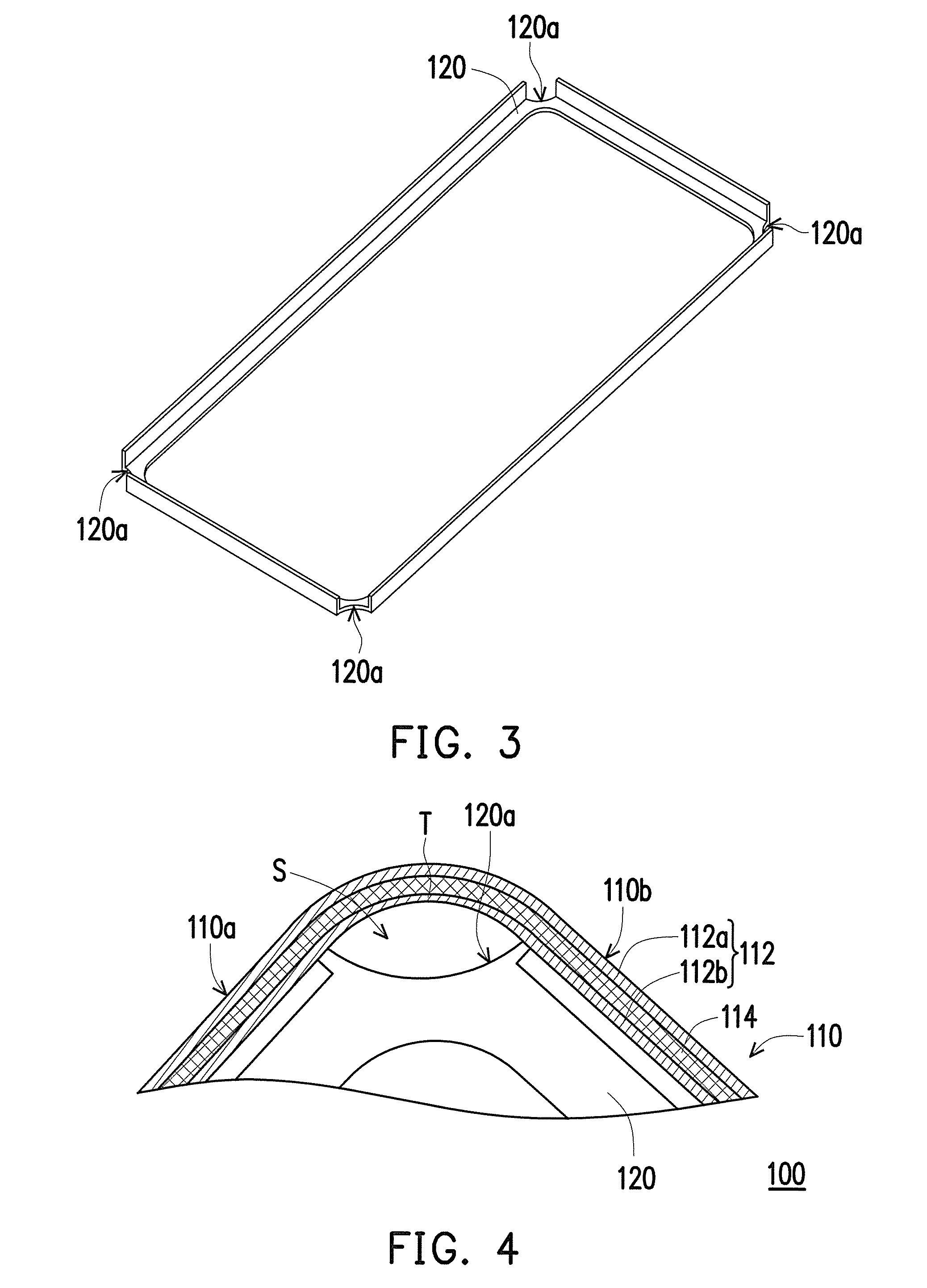
[0047]FIG. 2 is a partially enlarged diagram of the shell structure of FIG. 1. Referring to FIG. 1 and FIG. 2, the shell structure 100 of the present embodiment includes a casing 110. The casing 110 includes an elastic material structure 112 and a fiber structure 114. The fiber structure 114 is, for example, a woven fiber layer and is intermixed with elastic material structure 112. The elastic material structure 112 includes an outer layer str...


PUM

PropertyMeasurementUnit
Timeaaaaaaaaaa
Lengthaaaaaaaaaa
Thicknessaaaaaaaaaa

Abstract

A shell structure including a casing and a frame is provided. The casing includes an elastic material structure and a fiber structure, wherein the fiber structure is intermixed with the elastic material structure, and the casing has at least two sides adjacent to each other. The frame is wrapped by the casing, wherein the casing and the frame have at least one buffering space therebetween, and the buffering space is aligned to a border between the two sides. In addition, a manufacturing method of the shell structure is also provided.

Description

CROSS-REFERENCE TO RELATED APPLICATION[0001]This application claims the priority benefits of U.S. provisional application Ser. No. 62 / 097,021, filed on Dec. 26, 2014. The entirety of the above-mentioned patent application is hereby incorporated by reference herein and made a part of this specification.TECHNICAL FIELD[0002]The invention is related to a shell structure and a manufacturing method thereof, and more particularly, to a shell structure having an elastic material structure and a manufacturing method thereof.DESCRIPTION OF RELATED ART[0003]Advancement of semiconductor devices and display technology leads to continuous development of electronic devices towards compactness, capabilities for performing multiple functions, and portability. Common portable electronic devices include tablet PCs, smart phones and so forth.[0004]Taking the smart phones for an example, some products having crashworthiness for a demand are mostly emphasised on using material and structural designs to ...

Claims


Application Information

Patent Timeline
IPC IPC(8): H05K5/02H04M1/02B29C43/00
CPCH05K5/0217H04M1/0202B29C43/006
Inventor DENQ, BAR-LONGLI, CHUN-PINGCHIANG, CHIH-WENCHEN, CHIEN-CHU
Owner COMPAL ELECTRONICS INC
Learn More