Exhaust gas turbocharger

Active Publication Date: 2016-07-21
TURBO SYST SWITZERLAND LTD
View PDF18 Cites 1 Cited by
  • Summary
  • Abstract
  • Description
  • Claims
  • Application Information

AI Technical Summary

Benefits of technology

[0015]According to the invention, the external thread on the shaft has an undercut at the turbine end, allowing the component to be screwed on beyond the external thread in the axial direction when being mounted on the shaft, until it is in an unthreaded undercut in the mounted state. The component is then clamped on the shaft between the compressor wheel and an axial stop on the shaft by screwing the compressor wheel onto the external thread. Jamming in the region of the thread when clamping between the compressor wheel and the axial stop is thereby prevented in the mounted state. If the compressor wheel is rel

Problems solved by technology

In general, the rotating components are subject to very high circumferential forces and thus to high material stresses.
In some circumstances, defects in the structure of the material may lead to the compressor or turbine wheel bursting, sometimes with serious consequences for the housing parts surrounding the rotating components.
In the case of a compressor wheel breakdown due to the compressor wheel breaking apart, there is a loss of braking torque on the turbocharger rotor, as a result of which the now freely rotating turbine accelerates to overspeed and, when it reaches the speed at which it naturally bursts, fails.
The fragments, which are thrown outward with a high momentum, cause considerable damage to the surrounding housing parts and, in the worst case, may even pene

Method used


Image

  • Exhaust gas turbocharger
  • Exhaust gas turbocharger
  • Exhaust gas turbocharger

Examples


second embodiment

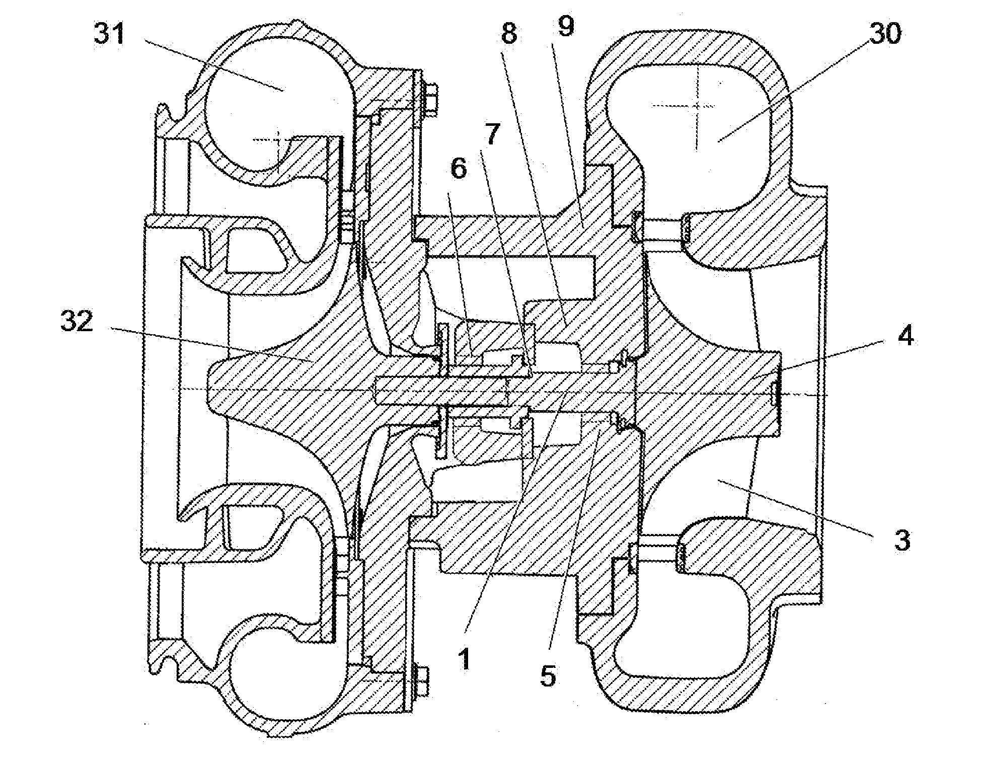
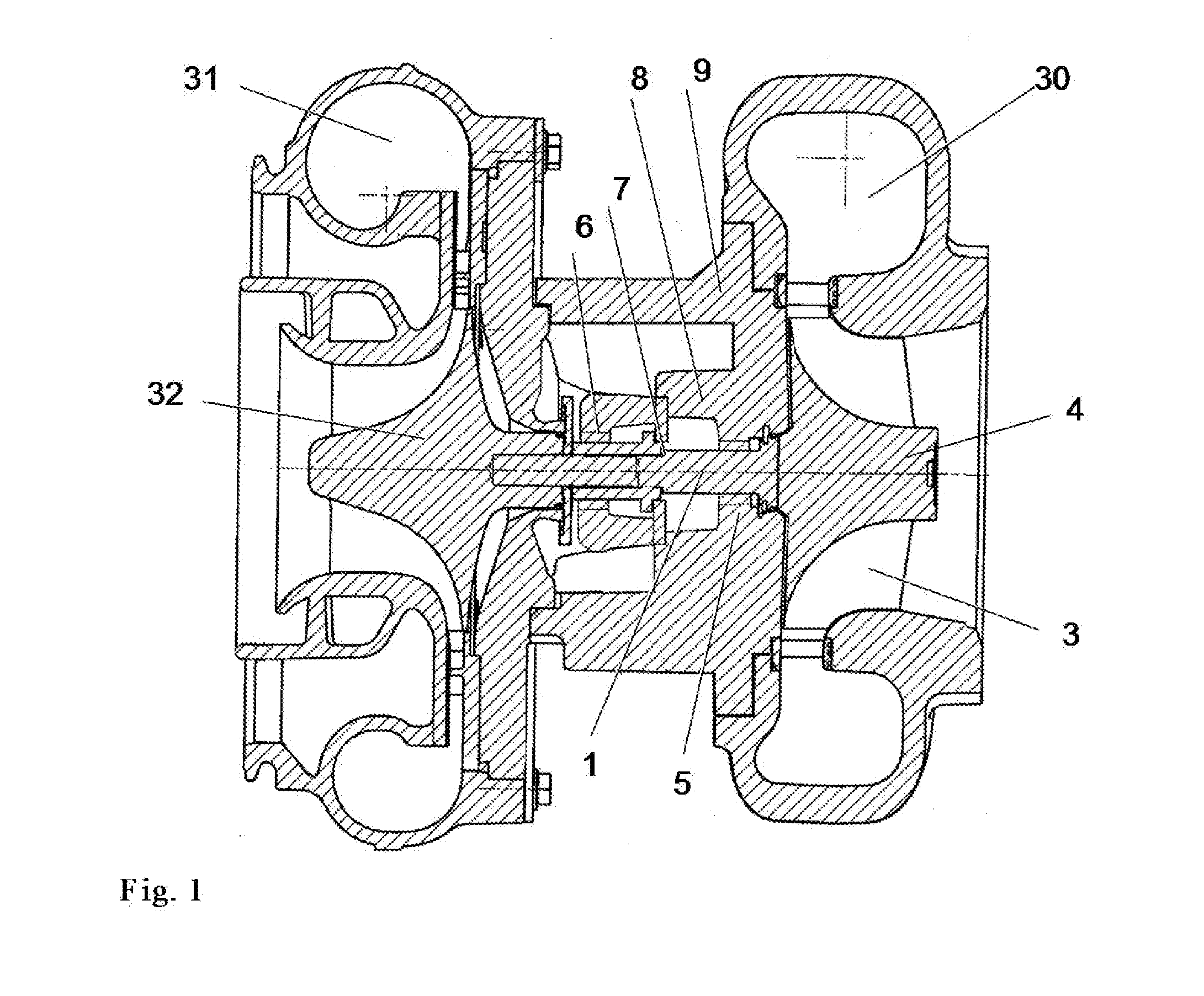
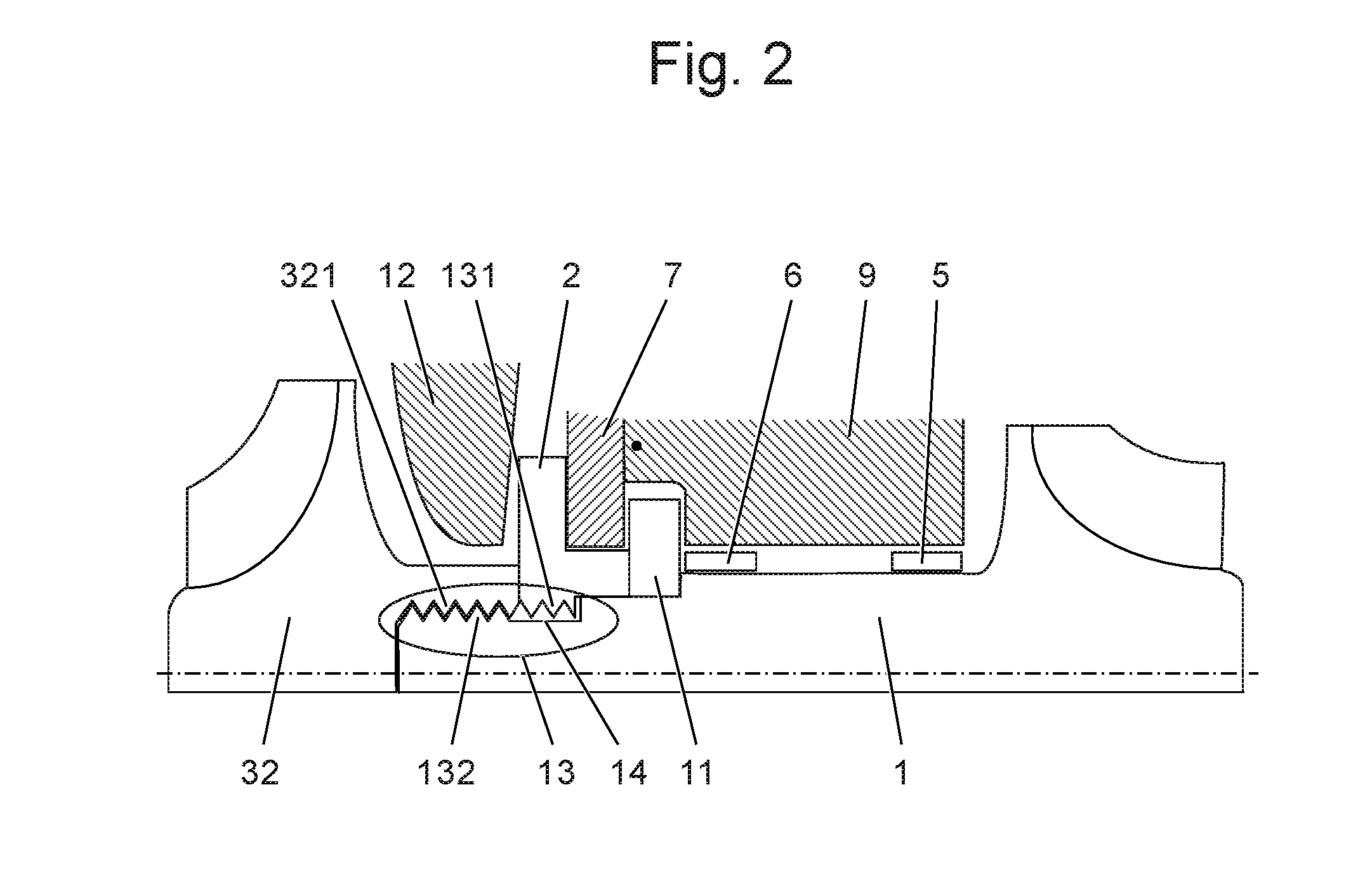
[0022]A first and second embodiment of a means according to the invention for axially securing the shaft 1 and the turbine wheel connected thereto for a turbine-side bursting concept of an exhaust turbocharger in the case of blade bursting comprises the device shown in FIGS. 2 and 3 and explained below.

[0023]The means according to the invention for axially securing the shaft 1 and the turbine wheel connected thereto comprises a component 2 having an internal thread 131, and an external thread 132 formed on the shaft 1. The component 2 is mounted on the shaft, the internal thread 131 of the component 2 and the external thread 132 on the shaft 1 thus jointly forming a screwed joint 13, wherein the smallest inside diameter of the internal thread 131 of the component 2 is smaller than the largest outside diameter of the external thread 132 of the shaft 1. During mounting, said component 2 can thus be screwed onto the shaft 1. In the mounted state, the component 2 serves as an axial secu...

first embodiment

[0025]An illustrative embodiment of the invention is depicted in FIG. 2. According to the invention, this consists of a sealing disk 2 having an internal thread 131 and of an external thread 132 formed on the shaft 1. In the illustrative embodiment, the external thread 132 formed on the shaft 1 has a reduced length in the axial direction of the shaft 1 compared with the first embodiment, as a result of which an unthreaded undercut 14 is formed at the turbine end of the external thread 132, said undercut having, according to the invention, a length in the axial direction that at least corresponds to the thickness of the sealing disk 2. In the mounted state, the internal thread 131 of the sealing disk 2 is situated in said undercut 14, thereby excluding unwanted jamming of the sealing disk 2 in the thread. During mounting, the shaft 1 is in turn screwed through the sealing disk 2 from the turbine side (from the right in FIG. 2) toward the compressor side (to the left) until the thread...


PUM


Abstract

The exhaust turbocharger comprises a turbine having a turbine wheel and a compressor having a compressor wheel. The turbine wheel and the compressor wheel are connected by a shaft rotatably mounted in a bearing housing. A means for axially securing the shaft and the turbine wheel connected thereto is provided between the compressor wheel and the turbine wheel, wherein this means for axial securing limits an axial movement of the shaft and of the turbine wheel connected thereto in the direction of the turbine in the event of the compressor wheel bursting.
The means for axially securing the shaft and the turbine wheel connected thereto comprises a component which is connected to the shaft or mounted on the shaft and is fixed in the axial direction in the housing. According to the application, this component for axially securing is screwed onto the shaft during mounting.

Description

TECHNICAL FIELD[0001]The invention relates to the field of exhaust turbochargers for pressure-charged combustion engines.[0002]It relates to an exhaust turbocharger having a turbine wheel and a compressor wheel, which are connected to one another by means of a shaft, wherein a means for axially securing the shaft and the turbine wheel connected thereto in the event of the compressor wheel bursting is provided between the compressor wheel and the turbine wheel.PRIOR ART[0003]Nowadays, it is standard practice to boost the power of a combustion engine (internal combustion engine) by using exhaust turbochargers which have a compressor that supplies air for the combustion process to the combustion chamber of the combustion engine and have an exhaust turbine in the exhaust tract of the combustion engine. Pressure-charging the combustion engine increases the volume of air and fuel in the combustion chambers (cylinders) and, as a result, a significant increase in the power of the combustion...

Claims


Application Information

Patent Timeline
IPC IPC(8): F04D29/62F01D5/06F04D29/28F02C6/12
CPCF04D29/626F02C6/12F05D2230/60F04D29/284F05D2220/40F01D5/06F01D5/025F01D17/12F01D25/16F01D25/18
Inventor MORATH, CHRISTOPHGANTERT, STEFAN
Owner TURBO SYST SWITZERLAND LTD
Why Eureka
Try Eureka