Gas purge unit and gas purge apparatus

a gas purge unit and gas purge technology, applied in the direction of cleaning process and apparatus, vacuum cleaners, chemistry apparatus and processes, etc., can solve the problems of inability to obtain sufficient shielding effect (curtain effect), inability to obtain desired characteristics, and oxidation of the surface of wafers, so as to reduce the number of parts, uniform quality of objects, and the effect of reducing the size of the uni

Active Publication Date: 2016-07-21
TDK CORPARATION
View PDF2 Cites 5 Cited by
  • Summary
  • Abstract
  • Description
  • Claims
  • Application Information

AI Technical Summary

Benefits of technology

The present invention provides a device for treating objects, such as wafers, with uniform quality. By achieving vertical gas exchange, the device achieves faster and more uniform processing. The device includes a single bidirectional blowout member that reduces the number of parts and contributes to downsizing of the unit. The bidirectional blowout member is positioned at the opening of the container and generates curtain flows from both lateral side line parts, which increases the effect of blocking the flow from the outside to the inside of the container. The first dedicated blowout member is positioned closer to the opening than the second dedicated blowout member to prevent interference between the two flows.

Problems solved by technology

It may become impossible to obtain desired characteristics at the time of completion of elements due to oxidation of the surface of such metal wirings.
However, when such an air enters into the container, surfaces of the wafers may become oxidized due to oxygen or water in the air.
The gas flow blown from the curtain nozzle is weak at a lower part of the opening surface, and a sufficient shielding effect (curtain effect) cannot be possibly obtained.
Thus, there is a problem that arrival rates for purge completion vary between upper and lower portions of the container.
There is also a problem that gas exchange cannot be ideally performed due to complexity of channels of purge gas within the container.
In such a case, for example, there is further a problem that oxygen or water concentration in the atmosphere varies between wafers placed at the lower portion of the container and wafers placed at the upper portion of the container, and that the wafers are thus processed unevenly in the subsequent manufacturing processes.

Method used


Image

  • Gas purge unit and gas purge apparatus
  • Gas purge unit and gas purge apparatus
  • Gas purge unit and gas purge apparatus

Examples


first embodiment

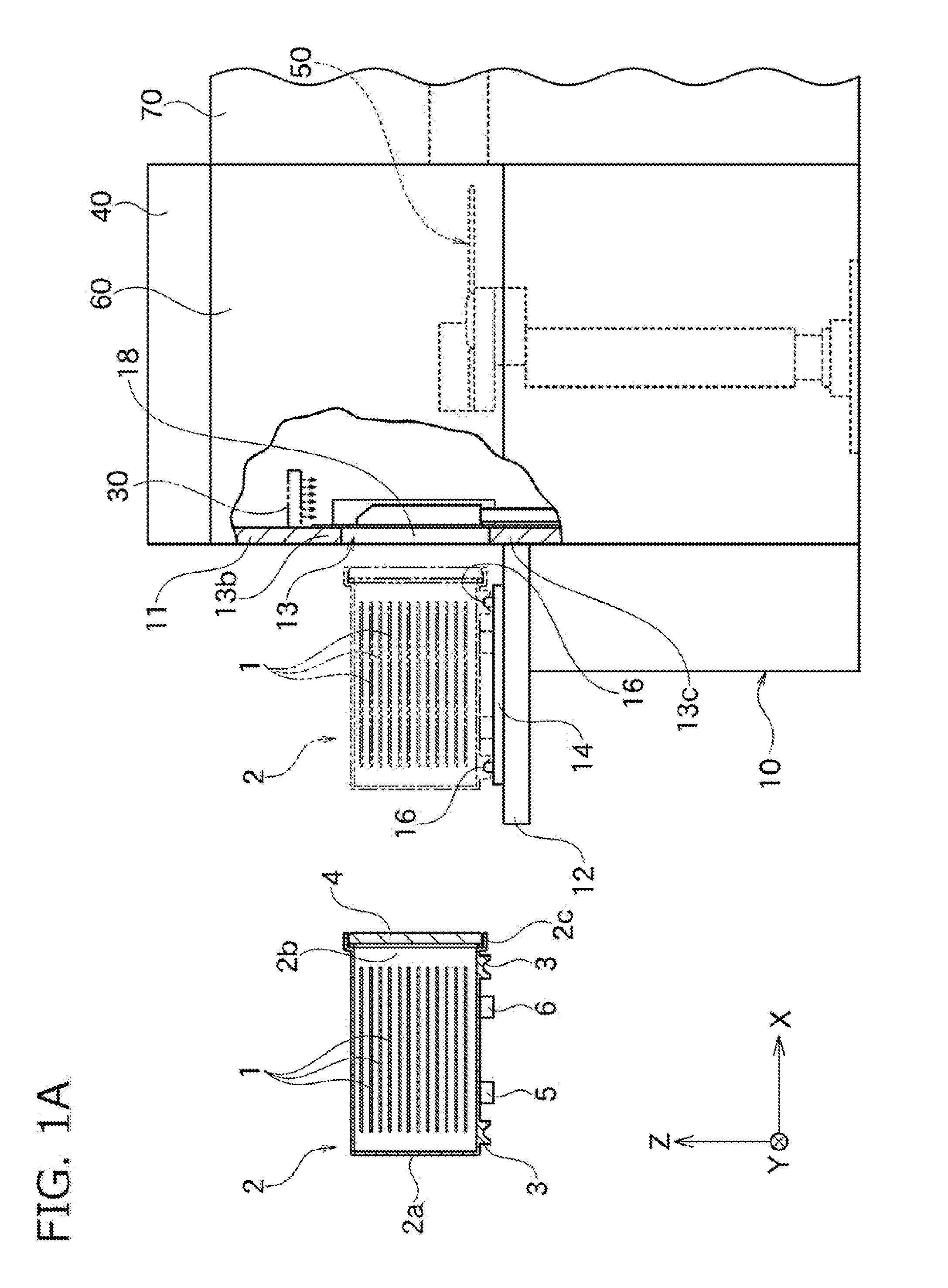
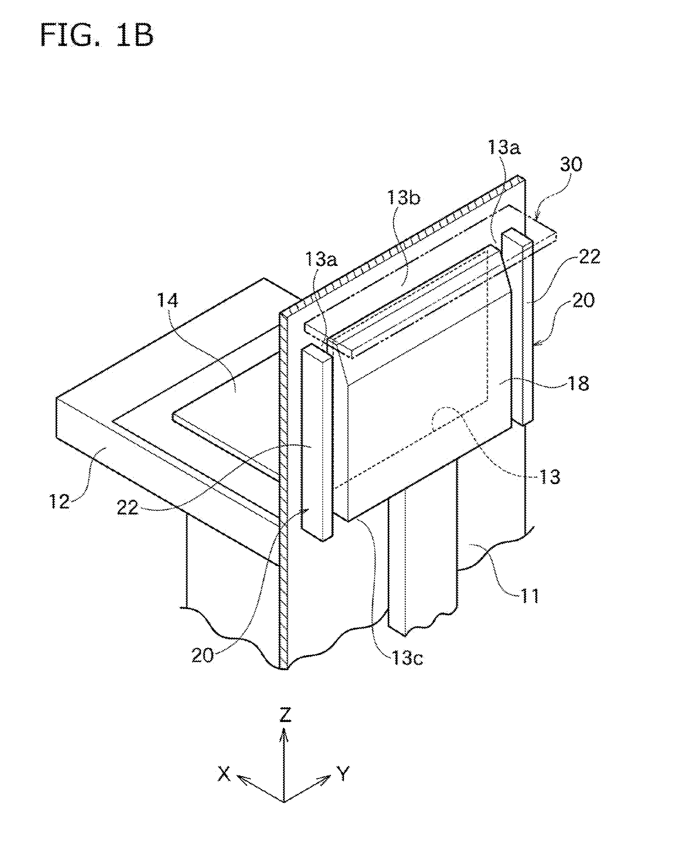
[0045]As shown in FIG. 1A, a load port apparatus 10 according to one embodiment of the present invention is connected to an intermediate chamber 60 such as an equipment front end module (EFEM). The load port apparatus 10 has an installation stand 12 and a movable table 14. The movable table 14 is movable on the installation stand 12 in the X-axis direction. Note that, in the figures, the X-axis represents a moving direction of the movable table 14, the Z-axis represents a vertical direction, and the Y-axis represents a direction vertical to the X-axis and the Z-axis.

[0046]A sealed transport container 2 can be detachably placed on a top of the movable table 14 in the Z-axis direction. The sealed transport container 2 is comprised of a pot or a FOUP etc. for transporting a plurality of wafers 1 while they are sealed and stored, and has a casing 2a. A space for housing the wafers 1 to be processed is formed inside of the casing 2a. The casing 2a has an approximately box-like shape with...

second embodiment

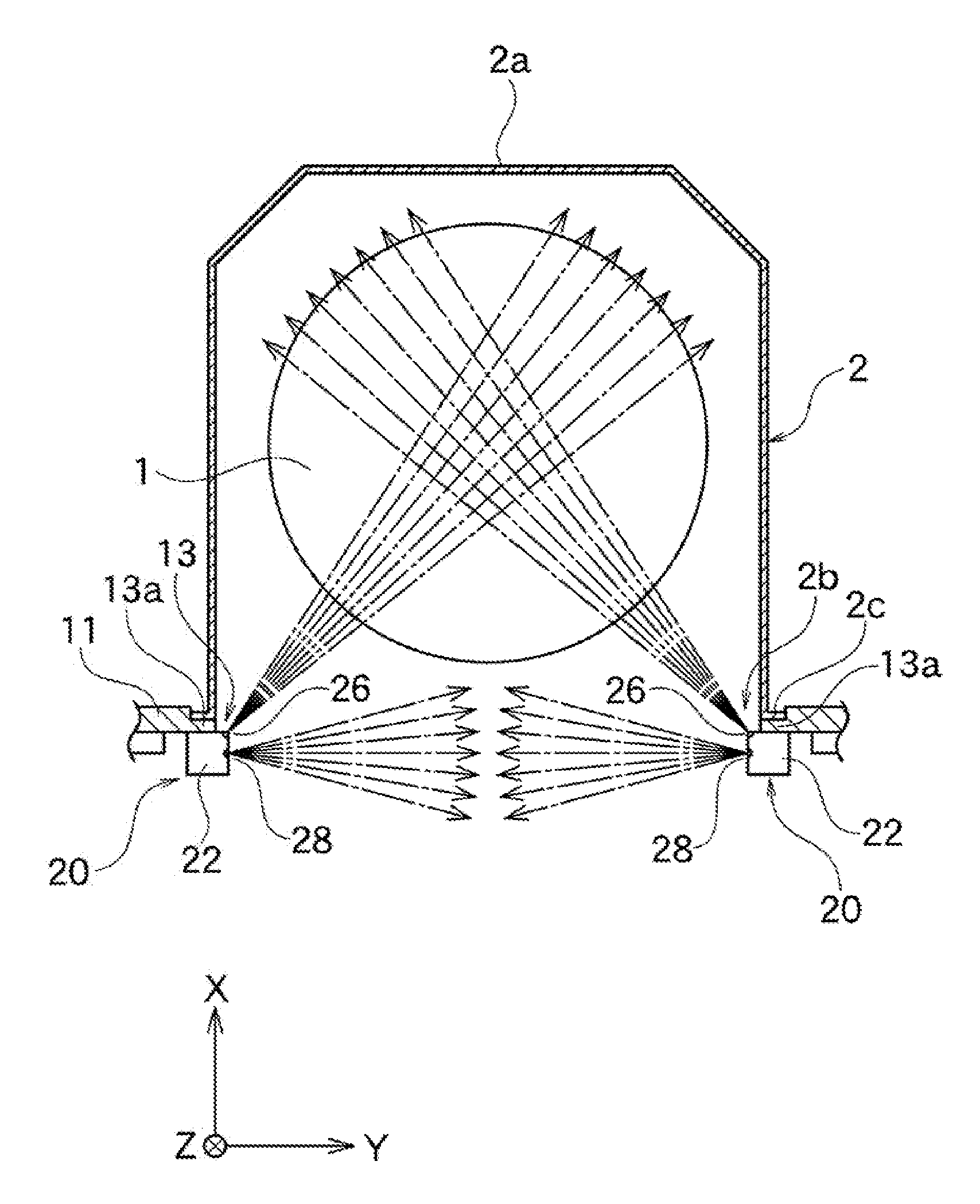
[0085]FIG. 4C shows a combination of gas purge units 20a according to another embodiment of the present invention. In this embodiment, as shown in FIG. 4C, first nozzle outlets 26 are formed on first dedicated blowout members 22α, and second nozzle outlets 28 are formed on second dedicated blowout members 22β. At the first dedicated blowout members 22α, the second nozzle outlets 28 are not formed, but only the first nozzle outlets 26 are formed. Similarly, at the second dedicated blowout members 22β, the first nozzle outlets 26 are not formed, but only the second nozzle outlets 28 are formed.

[0086]In the present embodiment, the gas purge unit 20a composes of the first dedicated blowout member 22α and the second dedicated blowout member 22β, and the first dedicated blowout members 22α are arranged closer to an opening 13 than the second dedicated blowout members 22β. In this arrangement, the curtain flow blown out from the second nozzle outlets 28 of the second dedicated blowout memb...

third embodiment

[0089]FIG. 4D shows a combination of gas purge units 20b and 20c according to another embodiment of the present invention. In this embodiment, as shown in FIG. 4D, a first nozzle outlet 26 is formed on a first dedicated blowout member 22α, and a second nozzle outlet 28 is formed on a second dedicated blowout member 22β.

[0090]In this embodiment, the gas purge unit 20b having no second dedicated blowout member 22β but having the first dedicated blowout member 22α is fixed on the inner surface of a wall 11 along the Z-axis direction of one of lateral side line parts 13a of an opening 13. Similarly, the gas purge unit 20c having no first dedicated blowout member 22α but having the second dedicated blowout member 22β is fixed on the inner surface of the wall 11 along the Z-axis direction of the other lateral side line part 13a of the opening 13.

[0091]In this embodiment, a container-inward flow is formed by only the first dedicated blowout member 22α, and a curtain flow is formed by only ...


PUM


Abstract

A gas purge unit 20 introduces a cleaning gas into a purging container 2 with an opening 2b therethrough. The gas purge unit 20 includes a first nozzle outlet 26 and a second nozzle outlet 28. The first nozzle outlet 26 blows out the cleaning gas from a lateral side line part of the opening 2b toward the inside of the purging container 2. The second nozzle outlet 28 blows out the cleaning gas from the lateral side line part of the opening 2b toward an opening surface of the opening 2b.

Description

BACKGROUND OF THE INVENTION[0001]1. Field of the Invention[0002]The present invention relates to a gas purge unit and a gas purge apparatus used for a manufacturing process of semiconductors, for example.[0003]2. Description of the Related Art[0004]In the manufacturing process of semiconductors, wafers housed in a wafer transfer container include ones on which metal wirings or so are formed, for example. It may become impossible to obtain desired characteristics at the time of completion of elements due to oxidation of the surface of such metal wirings. Thus, oxidation concentration inside the container is necessary to be kept at a low level.[0005]However, when wafers in a pod are brought to various processing apparatuses for performing a predetermined processing thereto, the inside of the container and the inside of the processing apparatuses are constantly kept in a connected condition. A fan and a filter are arranged at the upper area of a room where a transfer robot is arranged,...

Claims


Application Information

Patent Timeline
Patent Type & Authority Applications(United States)
IPC IPC(8): B08B9/093B08B5/02
CPCB08B5/02B08B9/093
Inventor IWAMOTO, TADAMASAEMOTO, JUN
Owner TDK CORPARATION
Why Eureka
Try Eureka