
Computed tomography having motion compensation

a computed tomography and motion compensation technology, applied in tomography, instruments, applications, etc., can solve the problems of non-rigid movement and inability to achieve the prior art, and achieve the effect of low deformation, effective compensation and iterative optimization convergent particularly quickly

Active Publication Date: 2016-07-21
SIEMENS HEALTHCARE GMBH
View PDF1 Cites 10 Cited by
  • Summary
  • Abstract
  • Description
  • Claims
  • Application Information

AI Technical Summary

Benefits of technology

The patent describes a method for improving the positioning of sensors in a detector by using multiple projections at different angles. Each projection is corrected to compensate for any deviation in the surface where it is placed. The corrected sensor positions are used to generate a volume model that improves the image quality and reduces distortion. The method is flexible and can be used to recreate curved or saddle-shaped detectors, or compensate for non-rigid movement of the body volume. Additionally, a special case of rigid movement is also taken into account, and a further correction vector is added to facilitate the convergence of the optimization process.

Problems solved by technology

What is not possible in the prior art is the compensation of flexible, non-rigid movements, that is to say deformations, of a body volume.
Such non-rigid movements prevent a consistent image reconstruction.

Method used


Image

  • Computed tomography having motion compensation
  • Computed tomography having motion compensation
  • Computed tomography having motion compensation

Examples


Embodiment Construction

[0047]The exemplary embodiments explained below are preferred embodiments. In the exemplary embodiments, however, the described components of the embodiments in each case represent individual features that should be regarded independently of one another, and which in each case also further develop the invention independently from one another and thus should be considered, even individually or in another combination than the one shown, as being a constituent part of the invention. Furthermore, the described embodiments can also be supplemented by further ones of the already described features.

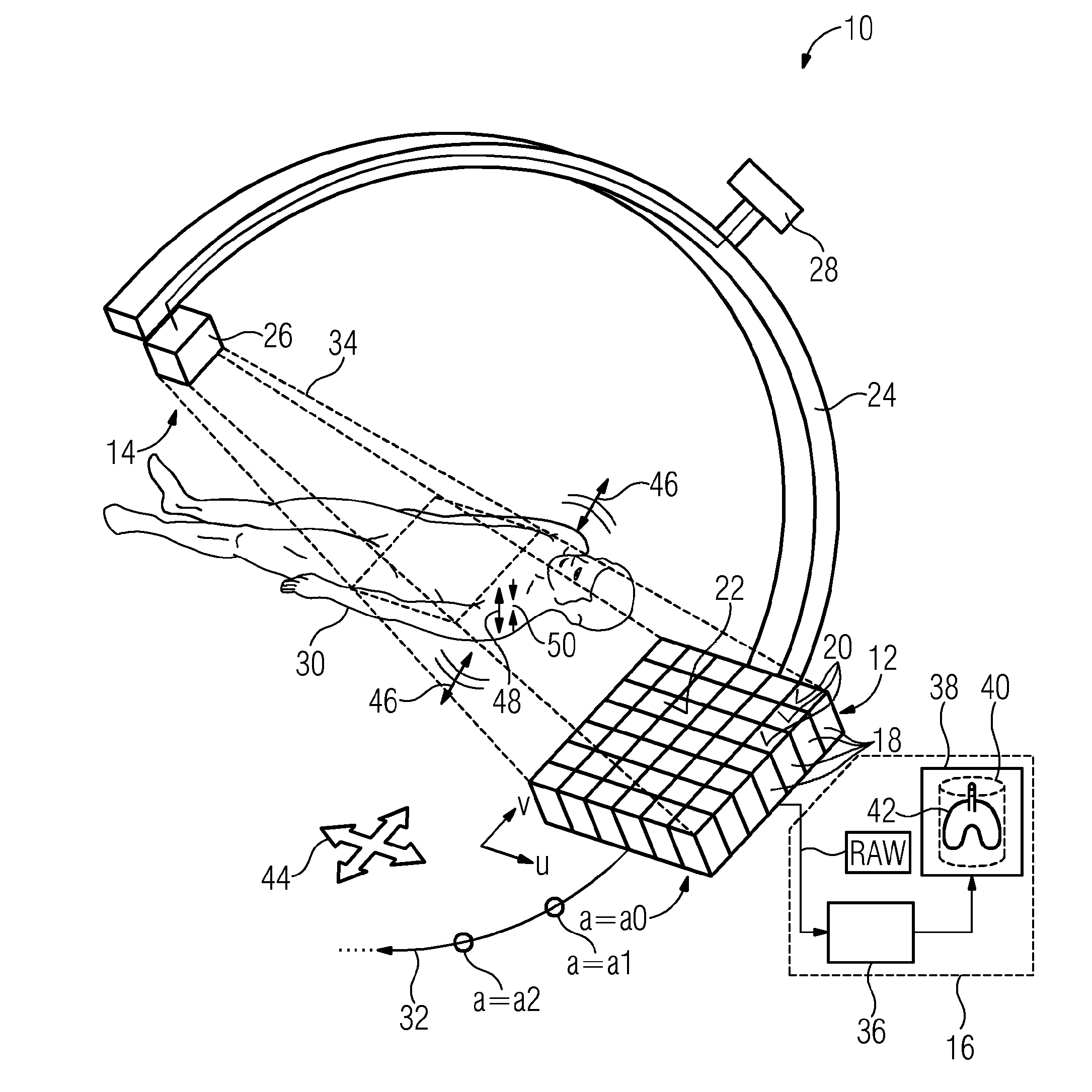
[0048]FIG. 1 shows a tomography system 10, which can be for example an X-ray C-arm system. The tomography system 10 can include a sensor device 12, a projection device 14 and an image generation device 16.

[0049]The sensor device 12 can include a detector having a plurality of radiation sensors 18, of which only some have reference signs in FIG. 1 for the sake of clarity. Sensor entry surfaces 20...


PUM


Abstract

The embodiments relate to a method for producing a digital volume model of a body volume by a sensor device, which sensor device includes a plurality of radiation sensors, of which each produces a pixel value in a projection. In order to produce the volume model, a plurality of projections from different projection angles (a) are produced and the volume model is computed from sensor positions of the radiation sensors and pixel values of the radiation sensors. For at least one projection angle (a), the sensor positions are corrected by a respective correction vector for rigid motion compensation. The problem addressed is that of also compensating the non-rigid motion of the body volume (i.e., the deformation) in the computation of the volume model. This problem is solved in that, in order to correct the sensor positions, the projection surface provided by the totality of the radiation sensors is divided into a plurality of sub-surfaces and a separate correction vector is determined for each of the sub-surfaces independently of each other.

Description

RELATED CASES[0001]The present patent document is a §371 nationalization of PCT Application Serial Number PCT / EP2013 / 067911, filed Aug. 29, 2013, designating the United States, which is hereby incorporated by reference.BACKGROUND[0002]The present embodiments relate to a tomography system and a method for generating a volume model of a body volume. The volume model can be used to generate, for example, a volume graphic of the body volume, that is to say for example of the interior of a patient's body. The volume model is formed on the basis of pixel values of a plurality of projections of the body volume, wherein the projections are generated on a projection surface from different projection angles. When computing the volume model from the projections, a motion performed by the body volume between the times of projection is compensated. The tomography system according to one embodiment may be designed, for example, as an X-ray-based computed tomography scanner.[0003]In order to gener...

Claims


Application Information

Patent Timeline
Patent Type & Authority Applications(United States)
IPC IPC(8): A61B6/00A61B6/03
CPCA61B6/5264A61B6/585A61B6/032A61B6/582
Inventor KYRIAKOU, YIANNIS
Owner SIEMENS HEALTHCARE GMBH
Learn More