
Predictively controlling an environmental control system

a control system and environmental technology, applied in the direction of instruments, heating types, static/dynamic balance measurement, etc., can solve the problem of not being concerned with energy efficiency, achieve the effect of improving the energy efficiency and reducing the length of the hvac system

Inactive Publication Date: 2016-07-14
GOOGLE LLC
View PDF4 Cites 54 Cited by
  • Summary
  • Abstract
  • Description
  • Claims
  • Application Information

AI Technical Summary

Benefits of technology

The patent describes a system and method for controlling an environmental control system using predictive control to improve energy efficiency and temperature comfort. The system includes a model of the structure and possible control scenarios to control the indoor temperature for a future period of time. The model uses a cost function to determine the value of each control scenario, which is based on factors such as the error between the setpoint temperature and the temperature predictions, the runtime of the environmental control system, and the length of the cycles. The system selects the control scenario with the highest value to apply to control the environmental control system. The technical effect of this patent is to provide a more efficient and effective way to control the environmental control system, resulting in improved energy efficiency and temperature comfort.

Problems solved by technology

Bang-bang control, however, is not concerned with energy efficiency or providing a more comfortable environmental temperature beyond maintaining the temperature of the structure within the target temperature band.

Method used


Image

  • Predictively controlling an environmental control system
  • Predictively controlling an environmental control system
  • Predictively controlling an environmental control system

Examples


Embodiment Construction

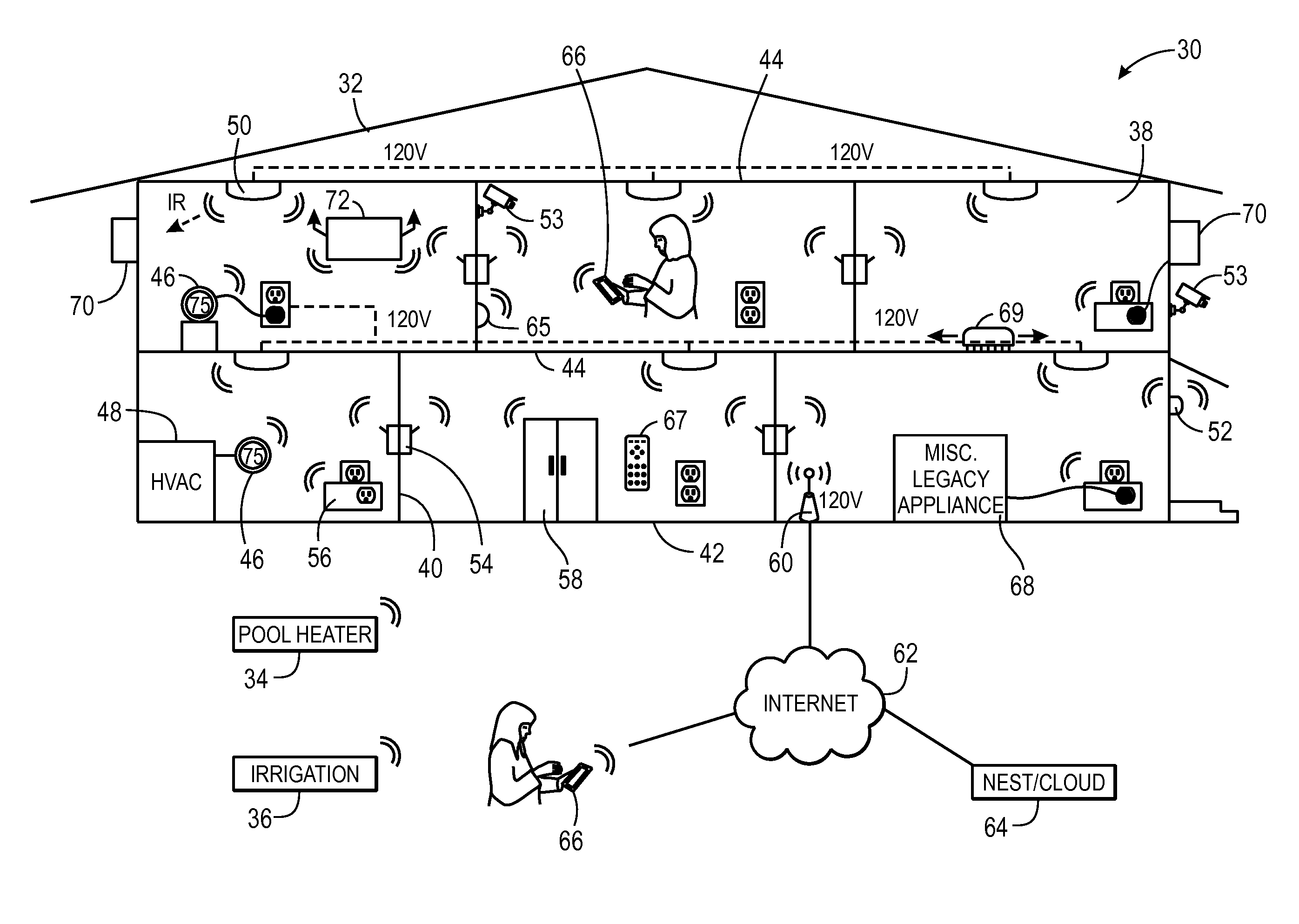
[0034]One or more specific embodiments of the present disclosure will be described below. In an effort to provide a concise description of these embodiments, all features of an actual implementation may not be described in the specification. It should be appreciated that in the development of any such actual implementation, as in any engineering or design project, numerous implementation-specific decisions must be made to achieve the developers' specific goals, such as compliance with system-related and business-related constraints, which may vary from one implementation to another. Moreover, it should be appreciated that such a development effort might be complex and time consuming, but would nevertheless be a routine undertaking of design, fabrication, and manufacture for those of ordinary skill having the benefit of this disclosure.

[0035]When introducing elements of various embodiments of the present disclosure, the articles “a,”“an,”“the,” and “said” are intended to mean that th...


PUM


Abstract

In an embodiment, an electronic device may include a power source configured to provide operational power to the electronic device and a processor coupled to the power source. The processor may be configured to generate temperature predictions using a model of a structure and possible control scenarios, determine a value of the temperature predictions and the respective possible control scenarios using a cost function, the cost function comprising weighted factors related to an error between a setpoint temperature and the temperature predictions, a length of runtime for an environmental control system (e.g., an HVAC system), and a length of environmental control system cycles. The processor may also be configured to select the control scenario with the highest value to apply to control the environmental control system. The control scenarios may be generated using upper confidence bound for trees (UCT).

Description

BACKGROUND[0001]This disclosure relates to controlling an environmental control system to improve the energy efficiency and / or temperature comfort level provided by the environmental control system.[0002]This section is intended to introduce the reader to various aspects of art that may be related to various aspects of the present techniques, which are described and / or claimed below. This discussion is believed to be helpful in providing the reader with background information to facilitate a better understanding of the various aspects of the present disclosure. Accordingly, it should be understood that these statements are to be read in this light, and not as admissions of prior art.[0003]Environmental control systems, such as heating, ventilation, and / or air conditioning (HVAC) systems, may manage a thermal environment of a structure, such as a residential or commercial building. Environmental control systems decide how to condition the structure properly, which may include varying...

Claims


Application Information

Patent Timeline
IPC IPC(8): F24F11/00G05B15/02F24D19/10
CPCF24F11/006F24F2011/0094F24F11/0034F24F11/0076F24F11/0086F24D19/1084G05B15/02F24F2011/0013F24F2011/0047F24F2011/0049F24F2011/0058F24F2011/0063F24F2011/0064F24F2011/0068F24F2011/0075F24F11/0012F24F11/30F24F2110/10F24F2110/12F24F2120/10F24F2140/60F24F2130/20F24F2130/00F24F2130/10F24F11/62F24F11/64F24F11/65F24F11/56F24F11/46F24F11/70F24F11/47F24F11/48F24F11/58F24F2120/00F24F11/526
Inventor HESTER, TODD ANDREWFISHER, EVAN JARMANKHANDELWAL, PIYUSH
Owner GOOGLE LLC
Learn More